Custom Search
|
|
  |
|
|
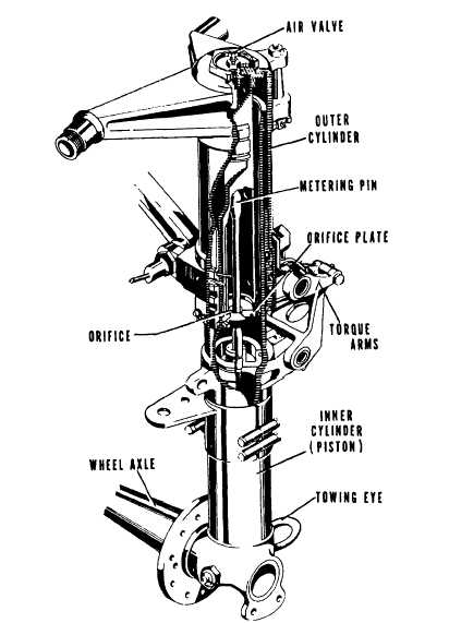
The shock strut absorbs the shock that otherwise would
be sustained by the airframe structure during takeoff,
taxiing, and landing. The air-oil shock strut is used
on all Navy aircraft. This type of strut is composed essentially
of two telescoping cylinders filled with hydraulic
fluid and compressed air or nitrogen. Figure 1-12
shows the internal construction of a shock strut. The
telescoping cylinders, known as cylinder and piston,
form an upper and lower chamber for the movement
of the fluid. The lower chamber (piston) is always
filled with fluid, while the upper chamber (cylinder)
contains the compressed air or nitrogen. An orifice
is placed between the two chambers through which
the fluid passes into the upper chamber during compression
and returns during extension of the strut. The
size of the orifice is controlled by the up-and-down movement
of the tapered metering pin. Whenever a load is placed on the strut because of the landing or taxiing of the aircraft, compression of the two strut halves starts. The piston (to which wheel and axle are attached) forces fluid through the orifice into the cylinder and compresses the air or nitrogen above it.
Figure 1-12.-Shock strut showing internal construction. When the strut has made a stroke to absorb the energy of the impact, the air or nitrogen at the top expands and forces the fluid back into the lower chamber. The slow metering of the fluid acts as a rubber to prevent rebounds. Instructions for the servicing of shock struts with hydraulic fluid and compressed air or nitrogen are contained on an instruction plate attached to the strut, as well as in the maintenance instruction manual (MIM) for the type of aircraft involved. The shock absorbing qualities of a shock strut depends on the proper servicing of the shock strut with compressed or nitrogen and the proper amount of fluid.RETRACTING MECHANISMS. -Some aircraft have electrically actuated landing gear, but most are hydraulically actuated. Figure 1-11 shows a retracting mechanism that is hydraulically actuated. The landing gear control handle in the cockpit allows the landing gear to be retracted or extended by directing hydraulic fluid under pressure to the actuating cylinder. The locks hold the gear in the desired position, and the safety switch prevents accidental retracting of the gear when the aircraft is resting on its wheels.A position indicator on the instrument panel indicates the position of the landing gear to the pilot. The position indicator is operated by the position-indicating switches mounted on the UP and DOWN locks of each landing gear.EMERGENCY EXTENSION. -Methods of extending the landing gear in the event of normal system failure vary with different models of aircraft. Most aircraft use an emergency hydraulic system. Some aircraft use pneumatic (compressed air or nitrogen), mechanical, or gravity systems, or a combination of these systems.
Figure 1-13.-Nose gear assembly. Nose Gear A typical nose gear assembly is shown in figure 1-13. Major components of the assembly include a shock strut, drag struts, a retracting mechanism, wheels, and a shimmy damper.The nose gear shock strut, drag struts, and retracting mechanism are similar to those described for the main landing gear. The shimmy damper is a self-contained hydraulic unit that resists sudden twisting loads applied to the nosewheel during ground operation, but permits slow turning of the wheel. The primary purpose of the shimmy damper is to prevent the nosewheel from shimmying (extremely fast left-right oscillations) during takeoff and landing. This is accomplished by the metering of hydraulic fluid through a small orifice between two cylinders or chambers.Most aircraft are equipped with steerable nose-wheels and do not require a separate self-contained shimmy damper. In such cases, the steering mechanism is hydraulically controlled and incorporates two spring-loaded hydraulic steering cylinders that, in addition to serving as a steering mechanism, auto-matically subdue shimmy and center the nosewheel. For more information concerning landing gear components (shock struts, shimmy dampers, power steering units, and brakes), you should refer to chapter 12 of this TRAMAN. |
 |
|
|