Custom Search
|
|
  |
|
|
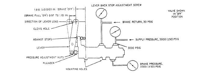
INDEPENDENT SYSTEM RESERVOIR Repair of this brake reservoir is limited to disassembly, cleaning, and replacement of high usage parts from a cure-date repair kit. These high usage parts consist of a new sight glass with its O-ring seal, washer, and retainer; a new filter, packing, and plug; and a new nameplate for the reservoir housing. Clean the reservoir inside and out with P-D-680 cleaning solvent. Use a fiber brush on threads. Dry the interior with clean, dry compressed air from a regulated low-pressure source. After the reservoir is cleaned and the cure-date repair kit parts have been installed, conduct a leakage test. This is accomplished by connecting a source of 25-psi air to the filler port and applying pressure. The reservoir should then be submerged in a tank of water for a minimum of 2 minutes. No leakage should be seen. Maintenance of these valves at organizational-level activities is limited to removal and replacement. After installation, rig the valves. Make an operational check of the brake system in accordance with the MIMs. Repair of the brake control valve consists of disassembly, cleaning, inspection, reassembly, and testing. Disassembly Perform the disassembly in a clean working area. As you remove parts, place them in a clean container for protection against dirt and damage. If the valve is to be disassembled for a considerable length of time, the parts should be protected from moisture. Note the method of lockwiring for reference during the reassembly process. Remove the end cap and the plunger assembly as a unit. Disassemble the end cap and plunger assembly for inspection, cleaning, and replacement of sealing devices. Remove the opposite end cap and remove the slide and sleeve assembly as a unit for disassembly. Cleaning Use P-D-680 cleaning solvent to clean parts. Except for the slide and sleeve, remove stubborn accumulations of dirt with a stiff bristle nonmetallic brush moistened in cleaning solvent. Dry all parts with low-pressure, dry, filtered air. NOTE: The slide and the sleeve assembly are precision lapped parts; they must be kept together as a matched set. You should take extra care to prevent damage during maintenance. Inspection Using a strong light and preferably some magnification, inspect all parts for scoring, nicks, cracks, burrs, excessive wear, corrosion, or damage. Carefully examine all packing grooves and lands for burrs and damage. The chrome plating of the plunger should be inspected for blisters, pinholes, flaking, or damage, and plating should be continuous. The sliding surfaces of the slide and sleeve should be free from scratches, burrs, or nicks. Inspect the seating edges of the slide for sharpness and freedom from nicks and burrs. Any damage to the slide and sleeve will necessitate replacement of both parts of the matched assembly. The holes in the valve-actuating lever are checked for elongation, and the roller that makes contact with the plunger is checked for smoothness and freedom from nicks and flat spots. Test springs for free length and test length versus test load in accordance with the spring data table provided in the 03 manual. Reassembly Before reassembly, immerse all internal parts in filtered, clean hydraulic fluid. Parts are reassembled while they are still wet. Reassembly is accomplished in the reverse order of disassembly. Upon completion of reassembly, adjust the lever backstop adjustment screw to the dimensions indicated in figure 12-42. Testing Figure 12-42 shows the operational test setup used to accomplish the variety of tests required to verify that the valve is ready for issue. A test stand capable of supplying hydraulic pressure from 0 to 4,500 psig pressure is required. Air is bled from the valve, and testing is conducted in accordance with the test procedures table provided in the MIMs and/or 03 manual. Tests include proof test, static pressure test, pressure drop test for internal leakage, and a complete operational test to verify power operation and adjustment. A test troubleshooting table can be found in the "Intermediate Repair" section of most MIMs and 03 manuals. Tables may be used to assist in isolating causes for malfunctions that result from repair action. After testing, fill the valve with preservative hydraulic fluid and plug all ports. Lockwire the lever backstop adjustment screw, the plunger end cap, and the end plug in the manner recorded before disassembly.
Figure 12-42.-Operational test setup-power brake valve. POWER/MANUAL BRAKE VALVE There is no daily or routine maintenance required on the power/manual brake valve other than a wipe down of the exposed portion of the rod. There are, however, certain repairs that can be effected in case of valve malfunction. These include replacement of seals, as required, tube, shaft, springs, or even the body in more serious cases. Tests are not required on the individual valve parts. After disassembly, cleaning, inspection, repair or replacement, lubrication, and complete reassembly have been accomplished, perform a bench test. This test will determine whether the unit satisfies the required minimum specifications. Test the power/manual brake valves on a test bench before installation in the aircraft. The test bench must be capable of supplying hydraulic fluid filtered through a 3-micron filter at a maximum pressure of 2,250 psi. During the test the room temperature should be 70 to 90F, and the fluid temperature 70 to 110F. The bench test is divided into the manual section and the power section. No particular sequence of performance of bench test is required, except that the proof pressure test of a section must precede the leakage test of that section. Bleed all air from the unit before it is tested. |
 
|
|
|
|
|
Integrated Publishing, Inc. - A (SDVOSB) Service Disabled Veteran Owned Small Business
|