Custom Search
|
|
  |
|
|
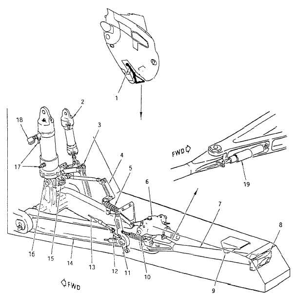
DAMPER CYLINDER.
The
representative arresting gear assembly employs a vertical damper cylinder and two horizontal dampers to dampen hook
motion caused by deck impact forces. See figure 12-58. Two centering spring assemblies maintain the hook in
the center position. With the arresting hook lowered, the centering springs are adjusted in the following manner: 1. Center the hook assembly.
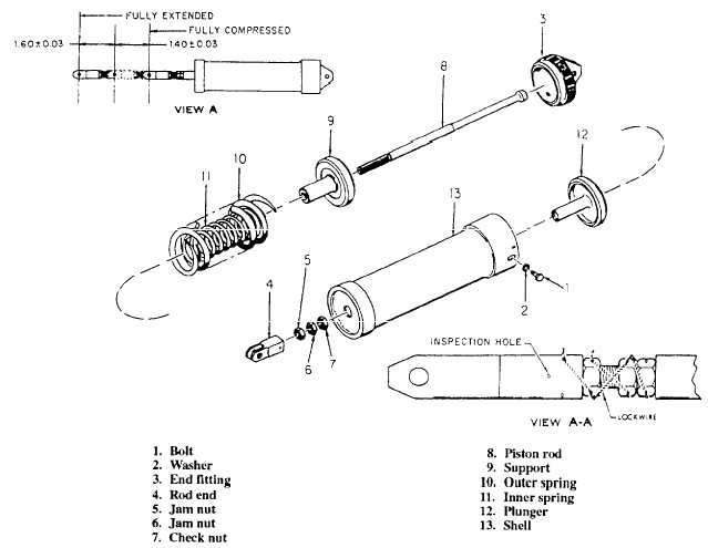
1. Arresting hook assembly Figure 12-58.Arresting gear assembly.
Figure 12-59.Centering spring. 2. Adjust the rod ends of both centering springs to reach the attaching pivot holes. Threads must be visible through the rod end inspection hole. See figure 12-59. 3. Tighten the nuts on the attaching bolts finger tight. Safety with cotter pins. 4. Torque the rod end jam nuts to 270-300 inch-pounds and safety with Iockwire, as shown in figure 12-59. 5. Check lateral movement of the hook in accordance with the procedures prescribed in the MIM. Intermediate-level maintenance of the centering springs consists of checking the disassembled parts for scoring, corrosion, nicks, structural deformation, or failure. Nonferrous parts are subjected to fluorescent penetrant inspection and ferrous parts to magnetic particle inspection. The diameter of all parts and the free length dimensions of the two springs, shown in figure 12-59, are checked against the values given in the parts tolerance tables provided in the MIM. WARNING Disassembly and assembly require extreme caution. The spring force is in excess of 500 pounds. Failure to observe the proper safety precautions could result in personnel injury.Post repair testing includes checking the breakout force required to extend and compress the springs. Force required is 560 60 pounds. The spring should extend 1.60 inches 0.03 inch and compress 1.40 inches 0.03 inch from neutral. |
 
|
|
|