Custom Search
|
|
  |
|
|
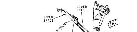
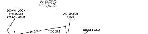
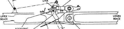
MECHANICAL LINKAGE The landing gear drag brace (fig. 12-12) consists of an upper and lower brace that is hinged at the center to
Figure 12-12.Landing gear drag brace adjustment. permit the brace to jackknife during retraction of the gear. The upper brace pivots on a trunnion attached to the wheel well overhead. The lower brace is connected to the lower portion of the shock strut outer cylinder. On the drag brace shown in figure 12-12, a locking mechanism is used where the lower and upper drag braces meet. Usually in this type of installation, the locking mechanism is adjusted so that it is allowed to be positioned slightly overcentered. You must be able to inspect and adjust landing gear braces and lccking mechanisms as specified in the applicable MIM. To adjust the drag brace shown in figure 12-12, you would first remove the cotter pin and nut (not shown) from the lock arm shaft. With the drag brace in the full extended position, rotate the eccentric bushings that are located on each end of the lock arm shaft. Both bushings must be rotated together to ensure that the high point of the eccentricity is the same on both bushings. Failure to do this may result in damage to the equipment or sluggish operation. The bushings maybe rotated in either direction until the end of the leek arm shaft, shown as point "A" in figure 12-12, is a distance of 0.003 inch to 0.015 inch from the striker. This clearance is checked with a feeler gauge. Other portions of the drag brace are nonadjustable, except for the length of its down leek cylinder. Figure 12-12 indicates the cylinder should be adjusted to a length of 12 3/8 inches. In the design of drag braces, the tendency has been directed toward lessening the adjustment requirements. In some installations, drag braces are manufactured to exact dimensions and do not require adjustments. NOSEWHEEL STEERING SYSTEMS Learning Objective: Recognize the types of nosewheel steering systems, their components, and the applicable main tenance requirements. Nose steering systems are hydraulically actuated and can be either electrically or mechanically controlled. The steering actuator serves the dual function of providing steering and dampening (when steering is not engaged). |
 
|
|
|
|
|
Integrated Publishing, Inc. - A (SDVOSB) Service Disabled Veteran Owned Small Business
|