Custom Search
|
|
  |
|
|
GMA Welding Equipment There arc numerous types and models of GMA welding equipment used in the Navy. Each must have a source of direct current reverse polarity (DCRP) welding current, a wire feed unit for feeding the wire tiller metal, a welding gun for directing the wire filler and shielding gas to the weld area, and a gas supply. Figure 15-47 shows GMA welding equipment. POWER SUPPLY. The recommended machine for gas metal-arc welding is a rectifier or motor generator that supplies direct current with normal limits of 200 to 250 amperes. Direct current reverse polarity is most generally used because it provides maximum heat for better melting, deeper penetration, and excellent cleaning action. Two types of direct-current power sources are used for gas metal-arc weldingthe constant-current type and the constant-voltage type. The constant-current power source is used if the controls and wire-driven mechanism control the arc length by varying the wire-drive speed. In this case, a change in the arc length causes a change in the arc voltage. The control circuit senses this change and varies the wire-feed speed to bring the arc length back to the desired value. When arc length is controlled through changes in welding current, constant-voltage power supplies are used. The wire-feed speed is constant. Any changes in arc length cause automatic changes in welding current, which compensate for the arc-length change. If the arc length becomes shorter, the welding current auto-matically increases. This causes the wire to melt faster and the arc length to increase. The reverse happens if the arc is lengthened during welding.WIRE FEEDING MECHANISM. The wire feeding mechanism automatically drives the electrode wire from the wire spool to the welding gun and arc at a uniform rate. The speed of the wire feeding mechanism is adjustable, so that the wire-feed speed can be set to equal the melting rate. If the drive unit is designed to be used with a constant-voltage power source, the speed is set before welding starts, and
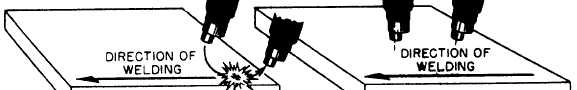
Figure 15-48.-Gas metal-arc welding. (A) striking the arc; (B) gun angle. remains constant during welding. If the unit is to be used with a constant-current voltage power source, the drive unit speed is varied automatically by an electronic control device. WELDING GUN. The function of the welding gun is to deliver the wire, shielding gas, and welding current to the arc area. Guns are either the push or pull type. The pull gun has drive rolls that pull the welding wire from the wire feeder, and the push gun has the wire pushed to it by drive rolls in the wire feeder itself. Both guns have a trigger switch that controls the wire feed and arc as well as the shielding gas. When the trigger is released, the wire feed, arc, and shielding gas stop immediately. With some equipment, a timer is included to permit the shielding gas to flow for a predetermined time to protect the weld until it solidifies. Guns are available with a straight or curved nozzle. The curved nozzle provides easy access to intricate joints and difficult to weld patterns.SHIELDING GAS. Shielding gases in the gas metal-arc process are used primarily to protect the molten metal from oxidation and contamination. Other factors must be considered, however, in selecting the right gas for a particular application. Shielding gas can influence arc and metal transfer characteristics, weld penetration, width of fusion zone, surface-shape patterns, welding speed, and undercut tendency. Inert gases, such as argon and helium, provide the necessary shielding because they do not form compounds with any other substance and are insoluble in molten metal. When used for welding ferrous metals, arc action may be erratic and the metal transfer globular. Therefore, it is necessary to add controlled quantities of reactive gases to achieve good arc action and metal transfer with these materials.Helium is preferable for welding thick materials, especially those with high heat conductivity, such as copper, aluminum, and some copper-base alloys. Helium has a higher ionization potential, which results in a greater weld heat at a given amperage. Argon is more suitable for use with lighter-gauge materials and materials of lower heat conductivity because it produces lower weld heat. GMA Welding Techniques Before you start to weld with GMA welding equipment, be sure that all controls are properly adjusted, all connections are correctly made, and that all safety precautions are being observed. Wear protective clothing, including a helmet with a suitable filter lens. Hold the welding torch at an angle of between 5 and 20 to the work, as shown in view B of figure 15-48. Support the weight of the welding cable and gas hose across your shoulder to ensure free movement of the welding torch. Hold the torch close to, but not touching, the work piece. Lower your helmet and squeeze the trigger on the torch. Squeezing the trigger starts the flow of shielding gas and energizes the welding circuit. The wire-feed motor is not energized until the wire electrode comes in contact with the work piece. Move the torch toward the work, touching the wire electrode to the work with a sideways scratching motion, as shown in view A of figure 15-48. To prevent sticking, it is necessary to pull the gun back quickly, about 1/2 inch, the instant contact is made between the wire electrode and the work piece. The arc will strike as soon as contact is made, and the wire-feed motor will feed the wire automatically as long as the trigger is held. To break the arc, just release the trigger. This breaks the welding circuit and also de-energizes the wire-feed motor. If the wire electrode sticks to the work when it strikes the arc, or at any time during welding, release the trigger and clip the wire with a pair of pliers or side cutters. A properly established arc has a soft, sizzling sound. The arc itself is about 1/4 inch long, or about one-half the distance between the gun nozzle and the work. When the arc does not sound right, you may need to adjust the wire-feed control dial or the welding machine itself. For example, a loud, crackling sound indicates that the arc is too short and the wire-feed speed is too fast. Correct this by moving the wire-feed speed dial slightly counter-clockwise. This decreases wire-feed speed and increases arc length. A clockwise movement of the dial has the opposite effect. With experience, you will soon be able to recognize the sound of the proper length of arc to use. The proper position of the welding torch and material is important. The flat position of the material is preferred for most joints because this position improves the molten metal flow, bead contour, and gives better gas protection. The alignment of the welding wire in relation to the joint is very important. The welding wire should be on the center line of the joint if the pieces to be joined are of equal thickness. If the pieces are unequal in thickness, the wire may be moved toward the thicker piece. Correct work and travel angles are necessary for correct bead formations. The travel angle may be a push angle or a drag angle, depending upon the position of the gun. If the gun is angled back toward the beginning of the weld, the travel angle is called a "drag" angle. If the gun is pointed ahead toward the end of the weld, the travel angle is called a "push" angle. When the gun is ahead of the weld, it is referred to as pulling the weld metal. If the gun is behind the weld, it is referred to as pushing the metal. The pulling technique is usually best for light gauge metals and the pushing technique for heavy materials. Generally, the penetration of beads deposited with the pulling technique is greater than with the pushing technique. Furthermore, since the welder can see the weld crater easier in a pulling action, he/she can produce high quality welds more consistently. On the other hand, pushing permits the use of higher welding speeds and produces less penetrating and wider welds. |
|
|
|