| Tweet |

Custom Search
|
|
  |
|
|
Quality Assurance/Analysis Quality assurance/analysis (QA/A) is responsible for the following: 1. Monitoring compliance with NDI personnel qualifications, certification/recertification requirements, safety precautions, and instructions. 2. Monitoring the organizations NDI training program to ensure it is current and comprehensive. Special emphasis should be placed on those areas of NDI that are accomplished by personnel other than those assigned Navy enlisted classification (NEC) 7225/military occupational specialty (MOS) 6044. Organizational Maintenance Activities O-levels responsibilities areas follows: 1. Request NDI I-level support as required. 2. Obtain IMA NDI services in all situations where NDI results are suspicious. 3. Have an NDI technician verify defects discovered by an NDI operator, whenever possible. 4. Inform the IMA, in advance, of scheduled NDI requirements. Include these requirements in the monthly maintenance plan. 5. O-level NDI technicians maybe assigned to the supporting IMA, as necessary, to maintain their proficiency and to augment IMAs NDI capabilities. NDI INSPECTION METHODS The various NDI methods serve as tools of prevention that allow defects to be detected before they develop into serious or hazardous failures. With the NDI methods, a trained and experienced technician can detect flaws or defects with a high degree of accuracy and reliability. It is important that you become fully knowledgeable of the capabilities of each method. It is equally important that you recognize the limitations of the methods. Some of the defects found by NDI include corrosion, leaks, pitting, heat/stress cracks, and discontinuity of metals. The following paragraphs will give a brief synopsis of the various NDI inspections. For further information on NDI procedures, you should consult the inspected by an NDI method. Magnetic Particle Inspection Magnetic particle inspection is a rapid, non-destructive means of detecting discontinuities in parts made of magnetic materials. If the part is made from an alloy that contains a high percentage of iron and can be magnetized, it is in a class of metals called "ferro-magnetic," and it can be inspected by this method. If the part is made of material that is nonmagnetic, it cannot be inspected by this method. The magnetic particle inspection method will detect surface discontinuities, including those that are too fine to be seen with the naked eye, those that lie slightly below the surface, and, when special equipment is used, the more deeply seated discontinuities. The inspection process consists of inducing a magnetic field into a part and applying magnetic particles, in liquid suspension or dry powder, to the surface being inspected. When the magnetic field is interrupted by a discontinuity, some of the field is forced out into the air above the discontinuity, forming a leakage field. The leakage field will be stronger and more concentrated the closer the discontinuity is to the surface. The presence of a discontinuity is detected by the ferromagnetic particles applied over the surface. Some of these particles will be gathered and held by the leakage field. This magnetically held collection of particles forms an outline of the discontinuity and indicates its location, size, and shape. Electric current is used to create or induce magnetic fields in magnetic materials. The magnetic lines of force are always aligned at right angles (90) to the direction of the current flow. The direction of the magnetic field can be altered, and it is controlled by the direction of the magnetizing current. The arrangement of the current paths is used to induce the magnetic lines of force so that they intercept and are as near as possible at right angles to the discontinuity. The magnetic field must be in a favorable direction to produce indications. When the flux lines are oriented in a direction parallel to a discontinuity, the indication will be weak or lacking. The best results are obtained when the flux lines are in a direction at right angles to the discontinuity. If a discontinuity is to produce a leakage field and a readable magnetic particle indication, the discontinuity must intercept the flux lines of force at some angle. When an electrical magnetizing current is used, the best indications are produced when the path of the magnetizing current is flowing parallel to the discontinuity, because the magnetic flux lines are always at an angle of 90 to the flow of the magnetizing current. The two types of magnetizing methods used are circular and longitudinal. CIRCULAR MAGNETIZATION. -Circular magnetization is used for the detection of radial discontinuities around edges of holes or openings in parts. It is also used for the detection of longitudinal discontinuities, which lie in the same direction as the current flow either in a part or in a part that a central conductor passes through. Circular magnetization derives its name from the fact that a circular magnetic field always surrounds a conductor, such as a wire or a bar carrying an electric current (fig. 15-3). The direction of the magnetic lines of force (magnetic field) is always at right angles to the
Figure 15-3.-Magnetic field surrounding an electrical conductor.
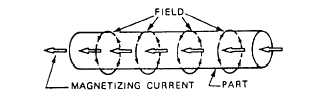
Figure 15-4.-Magnetic field in part used as a conductor.
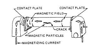
Figure 15-5.-Creating a circular magnetic field in a part. direction of the magnetizing current. An easy way to remember the direction of magnetic lines of force around a conductor is to imagine that you are grasping the conductor with your hand so that the extended thumb points parallel to the electric current flow. The fingers then point in the direction of the magnetic lines of force. Conversely, if the fingers point in the direction of current flow, the extended thumb points in the direction of the magnetic lines of force. Since a magnetic part is in effect a large conductor, electric current passing through this part creates a magnetic field in the same manner as with a small conductor (fig. 15-4). The magnetic lines of force are at right angles to the direction of the current as before. This type of magnetization is called "circular magnetization" because the lines of force, which represent the direction of the magnetic field, are circular within the part. To create or induce a circular field in a part with stationary magnetic particle inspection equipment, the part is clamped between the contact plates and current is passed through the part, as indicated in figure 15-5. This sets up a circular magnetic field in the part that creates poles on either side of any crack or discontinuity that runs parallel to the length of the part. The poles will attract magnetic particles, forming an indication of the discontinuity.
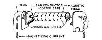
Figure 15-6.-Using a central conductor to circularly magnetize a cylinder.
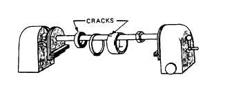
Figure l5-7.-Using a central conductor to circularly magnetize ringlike parts.
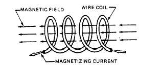
Figure 15-8.-Magnetic field in a part placed in a coil. On parts that are hollow or tubelike, the inside surfaces are as important to inspect as the outside. When such parts are circularly magnetized by passing the magnetizing current through the part, the magnetic field on the inside surface is negligible. Since there is a magnetic field surrounding the conductor of an electric current, it is possible to induce a satisfactory magnetic field by placing the part on a copper bar or other conductor. This situation is illustrated in figures 15-6 and 15-7. Passing current through the bar induces a magnetic field on both the inside and outside surfaces. |
 
|
|
|
|
|
Integrated Publishing, Inc. - A (SDVOSB) Service Disabled Veteran Owned Small Business
|