Custom Search
|
|
  |
|
|
Model HCT-10 Stationary Hydraulic Test
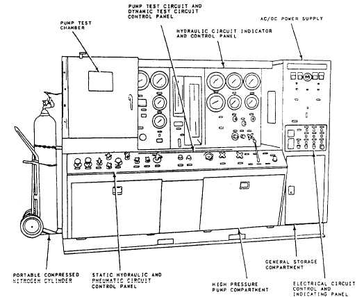
Stand Stationary hydraulic test stands, such as the Model HCT-10, are not part of the equipment allowance for most squadrons. Normally, they are issued to air stations and aircraft carriers for use by the supported squadrons. NOTE: The following information is for training purposes only. Do not use it as operating instructions for testing hydraulic or pneumatic components. For specific operat-ing instructions, you should refer to the applicable operational handbook, service, and overhaul instructions, or MIM.The Model HCT 10 test stand (fig. 4-16) is used to bench test aircraft hydraulic and pneumatic components, such as engine-driver hydraulic pumps, electrohydraulic flight control assemblies, double-acting hydraulic cylinders, pneumatic and hydraulic relief valves, hydropneumatic accumu-lators, and other components. The test stand consists of a nonportable cabinet assembly that contains a hydraulic system, a pneumatic system, and an electrical system. It must be connected to externally supplied electrical power, water, and compressed air. The cabinet assembly consists of a welded steel enclosure on a rigid base. Hinged doors and removable panels provide access to the interior. The test component work area is located below the center instrument and control panel. The bottom surface of the test component work area and the test chamber is shaped like a sink with perforated metal trays. The test chamber is made from a 1/4-inch steel plate with a hinged door containing a safety-type window. Most of the hydraulic and pneumatic system operating controls are located on a sloping panel along the front of the cabinet. The indicators are located on a panel above the work sink and the rear panel of the test chamber. The electrical system controls and indicators are located on a panel on the right-hand side of the cabinet. A partition separates
Hydraulic System The hydraulic system has two componentsa reservoir, which supplies fluid through a helical, screw-type boost pump and a filter to a variable volume, pressure-compensated, axial piston, high-pressure pump. Also, the hydraulic system has three circuits-the dynamic test circuit, the static test circuit, and the pump test circuit. DYNAMIC TEST CIRCUIT. The dynamic test circuit is used to test double-acting hydraulic cylinders and other components requiring combined pressure and flow.STATIC TEST CIRCUIT. The static testPUMP TEST CIRCUIT. The pump test circuit supplies controlled pressure and flow to a variable-displacement, reversible-rotation, hydraulic motor that, in turn, supplies power for driving hydraulic pumps during tests, |
 
|
|
|