|
PROCEDURES.
When failure
occurs in a flexible hose equipped
with swaged end fittings, the unit
is generally replaced without attempting a repair. The
correct length of hose, complete with factory-installed
end fittings, is drawn from supply. When
failures occur in hose assemblies equipped with
reusable style end fittings, the fabrication of the replacement
unit is the function of the intermediate and
depot organization levels. Undamaged end fittings
on the old length of hose maybe removed and reused;
otherwise, new fittings must be drawn from supply
along with a sufficient length of hose. The
following assembly procedures are for instructional
purposes only. When fabricating hose assemblies,
refer to the The
first step is to determine the necessary hose length
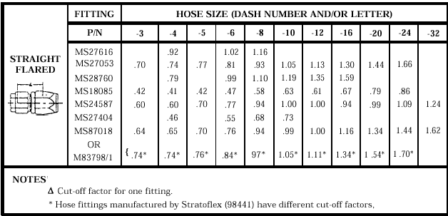
from table 5-2 and figure 5-10. Wrap the circumference
of the hose with masking or plastic electrical
tape at the cutoff to prevent flare-out of braid
if the hose outer cover is wire braid. Hose with rubber
or fabric outer cover does not require wrapping
Table 5-2.Hose Cutoff Factor
(In Inches)


Figure
5-10.Determining hose assembly length.

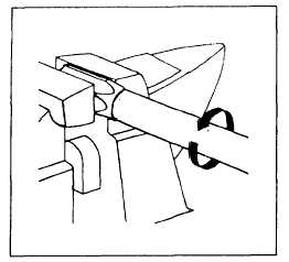
Figure 5-11.Hose insertion.
with tape. Measure the hose to the required length and
cutoff the square, using the cutoff machine (fig.
5-7). Blow the hose clean with filtered shop air after
cutting. Remove the tape and the clamp socket in
a vise (fig. 5-11). Do not overtighten vise on thin-walled
lightweight fittings. Screw the hose counterclockwise
into the socket using a twisting, pushing
motion until the hose bottoms on the socket shoulder.
Back the hose out 1/4 turn. Assemble the nipple
and nut with a standard adapter of the same size
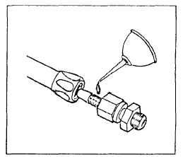
and thread (fig. 5-12). Lubricate the inside bore of
the hose and the outside surface of the nipple with hydraulic
fluid, MIL-H-5606, MIL-H-83282, or MIL-H-6083
(fig. 5-13). Clamp the socket with the hose
into a vise. Insert the nipple assembly into the hose
and socket by using a wrench on the hex of the

Figure
5-12.Nipple and nut assembly.

Figure
5-13.Assembly lubrication.
insertion tool. Turn the nipple assembly clockwise until
the nut-to-socket gap is between 0.005 and 0.031 inch.
The gap allows the nut to turn freely about its axis
(fig. 5-14). Remove the insertion tool from the assembly.
Repeat the procedure for hose assemblies with
straight fittings on both ends.
|


|

