Custom Search
|
|
  |
|
|
HYDRAULIC/PNEUMATIC POWER
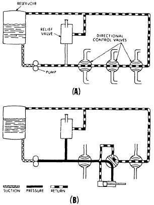
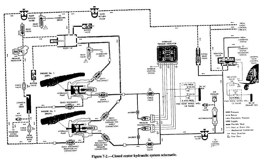
SYSTEMS System design must prevent the failure of a single part, such as a pump, pressure line, or filter, from disabling the aircraft. Special consideration is given to the hydraulic flight control system. System design specifications require two separate systems for operating the primary flight controls. All aircraft that use hydraulically operated flight controls have at least two hydraulic power systems. The systems supply pressure to the utility or normal system in addition to the flight controls. The flight control portion is given pressure priority by an isolation valve. This design feature isolates nonessential flight functions and prevents loss of hydraulic fluid in the event of utility or normal system rupture. As a minimum requirement, filters are provided in each system pressure line, return line, and pump bypass or case drain line. Where hydraulic sequencing is critical, each sequence valve is protected from contamination in each direction of flow by a screen-type filter. The filter is usually included as a part of the sequence valve. The pressure line falters clean all fluids before they enter any major equipment. If there are only two hydraulic systems, the primary system is known as the No. 1 power control system (PC-1). The system supplying the other half of the flight control tandem actuating mechanisms and the utility hydraulic system is known as PC-2. The PC-2 system is also known as the combined hydraulic system. If there are three hydraulic power systems, they are generally identified as PC-1, PC-2, and utility system. Some manufacturers label the utility system PC-3. Each system has its own reservoir, hydraulic pump(s), and plumbing. Military specifications, MIL-H-5440 (series), provide complete design, installation, and data requirements for aircraft hydraulic systems. These specifications provide reference to all other specifications concerning aircraft hydraulic systems. Items such as hose assemblies, hose support requirements, minimum bend radii, types of pumps, and types and classes of systems are found in the specifications. Many maintenance instruction manuals (MIMs) refer to aircraft hydraulic systems as being open center or closed center systems. The following paragraphs provide a discussion of these systems. Open Center An open center system is one having fluid flow, but no pressure in the system when the actuating mechanisms are idle. The pump circulates the fluid from the reservoir, through the selector valves, and back to the reservoir. Figure 7-1 shows a basic open center system. The open center system may employ any number of subsystems, with a selector valve for each subsystem. Unlike the closed center system, the selector valves of the open center system are always connected in series with each other. In this arrangement, the system pressure line goes through each selector valve, Fluid is always allowed free passage through each selector valve and back to the reservoir until one of the selector valves is positioned to operate a mechanism. When one of the selector valves is positioned to operate an actuating device, fluid is directed from the pump through one of the working lines to the actuator. See view B of figure 7-1. With the selector valve in this position, the flow of fluid through the valve to the reservoir is blocked. The pressure builds up in the system to overcome the resistance and moves the piston of the actuating cylinder, The fluid from the opposite end of the actuator returns to the selector valve and flows back to the reservoir. Operation of the system following actuation of the component depends on the type of selector valve being used. Several types of selector valves are used in conjunction with the open center system. One type is both manually engaged and manually disengaged. First the valve is manually moved to an operating position. Then, the actuating mechanism reaches the end of its operating cycle, and the pump output continues until the system relief valve relieves the pressure. The relief valve unseats and allows the fluid to flow back to the reservoir. The system pressure remains at the relief valve set pressure until the selector valve is manually returned to the neutral position. This action reopens the open center flow and allows the system pressure to drop to line resistance pressure. The manually engaged and pressure disengaged type of selector valve is similar to the valve pre-viously discussed. When the actuating mechanism reaches the end of its cycle, the pressure continues to rise to a predetermined pressure. The valve auto-matically returns to the neutral position and to open center flow. Closed Center In the closed center system, the fluid is under pressure whenever the power pump is operating. Figure 7-2 shows a complex closed center system.
The power pump may be one used with a separate pressure regulator control. The power pump may be used with an integral pressure control valve that eliminates the need for a pressure regulator. This system differs from the open center system in that the selector or directional control valves are arranged in parallel and not in series. The means of controlling pump pressure will vary in the closed center system. If a constant delivery pump is used, the system pressure will be regulated by a pressure regulator. A relief valve acts as a backup safety device in case the regulator fails. If a variable displacement pump is used, system pressure is controlled by the pumps integral pressure mechanism compensator. The compensator automatically varies the volume output. When pressure approaches normal system pressure, the compensator begins to reduce the flow output of the pump. The pump is fully compensated (near zero flow) when normal system pressure is attained. When the pump is in this fully compensated condition, its internal bypass mechanism provides fluid circulation through the pump for cooling and lubrication. A relief valve is installed in the system as a safety backup. An advantage of the open center system over the closed center system is that the continuous pressurization of the system is eliminated. Since the pressure is built up gradually after the selector valve is moved to an operating position, there is very little shock from pressure surges. This action provides a smoother operation of the actuating mechanisms. The operation is slower than the closed center system, in which the pressure is available the moment the selector valve is positioned. Since most aircraft applications require instantaneous operation, closed center systems are the most widely used. Power systems are designed to produce and maintain a given pressure. The pressure output of most of the Navys high-performance aircraft is 3,000 psi. The hydraulic system, shown in figure 7-2, is an example of a representative 3,000 psi hydraulic power system. The aircraft has three independent hydraulic power systems. The two primary systems are the flight hydraulic power system and the combined hydraulic power system. These systems are pressurized by two independent engine-driven hydraulic pumps on each engine. The auxiliary power system also operates on 3,000 psi pressure. It is pressurized by the hydraulic hand pump and/or the electric motor-driven hydraulic pump. The auxiliary power system is similar to the combined hydraulic power system. The primary difference is that the combined system supplies hydraulic pressure to utility hydraulic circuits and the flight controls. The hydraulic control valves and actuators that operate the primary flight controls are of the tandem construction type. This design permits operation from either or both of the two power systems. With this arrangement, either engine can fail or be shut down without complete loss of hydraulic power to either system. The flight system reservoir supplies fluid to the two engine-driven flight system pumps. The combined system reservoir supplies fluid to the two engine-driven combined system pumps and to the auxiliary hydraulic power system. Both reservoirs are of the pressurized piston type. They are pressurized by engine bleed air during engine operations and by an external air (nitrogen) source during maintenance operations. Hydraulic system pressure is indicated on the integrated hydraulic pressure indicator. This indicator displays the output pressure of the flight and combined hydraulic power systems. The flight hydraulic power system provides power for the operation of the rudder, stabilizer, and flaperons. It also provides power for operation of the automatic flight control system actuators, which are an integral part of the rudder and stabilizer control surface actuators. The flight hydraulic system also controls the automatic operation of the isolation valve. This valve is a part of the combined hydraulic system. The combined hydraulic power system consists of two parallel circuitsone to power the primary systems and the other to power the secondary systems. The primary system consists of spin recovery, rudder, stabilizer flaperon, speed brakes, and electric ram air turbine systems. The secondary system consists of wing slats, wing flaps, wing fold, landing gear, arresting gear, wheel brakes, nosewheel steering, and the nose strut locking systems. The isolation valve shuts off flow to the secondary systems during flight and limits the combined systems pressure requirements to operation of the primary circuit. Operation of the isolation valve is both automatic and manual. The reservoir pressurization system provides the reservoir with a differential pressure of 40 psi to prevent engine-driven pump cavitation. The pressure is maintained at 40 psi by the air regulator. In the event of regulator failure, the relief valve installed between the regulator and the reservoir prevents overpressurization. The relief valve opens at 50 psi. The chemical air drier removes excessive moisture from the bleed air. Dry, clean air is sent to the reservoir through the check valve, air regulator, and relief valve. TWO bleeder valves are installed in the flight and combined system reservoirs. One is found on the air side of the reservoir and the other on the fluid side. The air side valve permits the bleeding of air pressure during system maintenance. It allows the bleeding of any hydraulic fluid seepage past seals to the air side. The fluid side bleeder reduces excessive fluid level and bleeds air from the fluid side. Quick-disconnect fittings in the hydraulic power systems permit easy pump or engine removal without loss of fluid to the system. The fittings connect ground hydraulic test stands for maintenance purposes. The pump disconnects should not be forced together against the back pressure of a pressurized reservoir or system. Forcing disconnects together may result in damaged seals in the male ends of the disconnects. When the disconnects do not slide in smoothly, they should be removed and checked for proper seating of the O-rings. Replace seals if they are damaged. The seal goes on top of the O-ring. When the disconnects are uncoupled, the ends not being used should be properly protected from dirt and other contamination. Use only approved metal closures. |
 
|
|
|
|
|
Integrated Publishing, Inc. - A (SDVOSB) Service Disabled Veteran Owned Small Business
|