Custom Search
|
|
  |
|
|
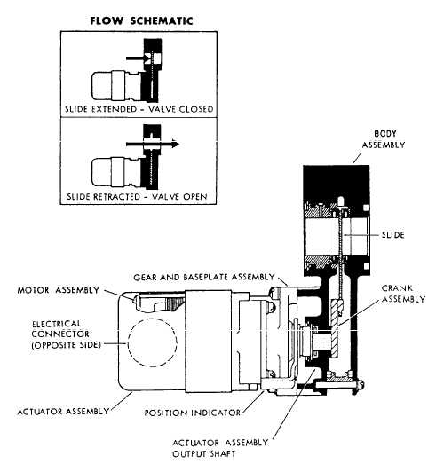
Motor Operated Shutoff Valves The purpose of the shutoff valve, shown in figure 7-26, is to shut off the flow of hydraulic fluid to the engine in case of an engine fire. The valve may also be used to great advantage during replacement of line quick-disconnects and other maintenance functions. There are usually other shutoff valves, identical in appearance, installed within the same area that prevent oil and fuel from reaching the engine in case of an engine fire. When the shutoff valve is energized, an electrical impulse is applied to the electrical connector on the motor, which converts the electrical energy into rotary motion of the actuator output shaft by the means of a gear train. his rotary motion is then transmitted to the shaft, which couples the actuator output shaft to the crank assembly. The crank assembly then transmits the rotary motion of the shaft to the linear motion of the slide. The amount of rotation of the valve output shaft is controlled by means of limit switches in the motor and gear assembly, which interrupt current to the motor. When the valve is in the open position, the slide is retracted into the valve body, thus permitting the flow of hydraulic fluid through the valve. When the valve is in the closed position, the slide is positioned between the inlet and outlet ports, thus shutting off the fluid flow. The valve incorporates a visual position indicator (on the valve itself). The indicator is mechanically con-nected to the operating parts of the valve and provides a positive indication of the position of the valve. CAUTION Operating an engine with the fire wall shutoff valve closed could cause severe damage to the engine-driven pump.Electric Solenoid Shutoff Valve The shutoff valve, shown in figure 7-27, is used to shut off the fluid flow to selected subsystems of a
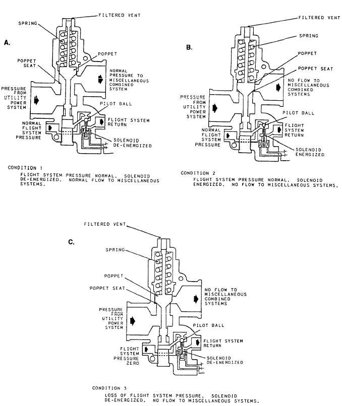
CONDITION ONE (LANDING). Flight control system pressure normal, switch in the landing position, solenoid deenergized, and the pilot ball on its lower seat, blocking the return port of the flight control system. See Figure 7-27, View A. In this condition, the pressure of the flight control system is allowed to act upon the lower working area of the poppet, moving it upward off its seat and compressing the poppet spring. This action will allow the fluid of the utility system to flow downstream from the location of the valves to the landing gear, flaps, speed brakes, etc.CONDITION TWO (FLIGHT). Flight control system pressure normal, switch in the flight position, solenoid energized, and the pilot ball on its upper seat, preventing the pressure of the flight control system from working on the lower working area to the poppet. See Figure 7-27, View B. In this condition the return port of the flight system is open. The poppet spring will move the poppet onto its seat, preventing the fluid fron the utility system from flowing downstream from the location of the valve. This allows all available fluid to be directed to the components of the utility section, such as the ailerions, rudder, stabilizer, spoilers, of the flight control subsystem.CONDITION THREE (EMERGENCY). Failure of the flight control hydraulic system. The flight control system pressureis 0 psi, and the utility system pressure is normal. During this condition, the poppet will remain on its seat, because the pressure of the flight control system is not available to work on the lower working area of the poppet to move it up to open the valve. See Figure 7-27 View C.Failure of the electrical system to the electro-hydraulic shutoff valve. The pressures of the flight control and utility systems are normal, and there is no electrical power to the solenoid In this conditon, the solenoid cannot be energized, the polit ball will remain on its lower seat, and the pressure of the flight control system will work on the lower working area. This holds the poppet of its seat and allows the pressure of the utility systems to flow downstream from the location of the valves. |
|
|
|