Custom Search
|
|
  |
|
|
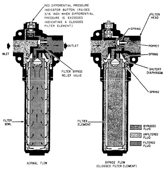
Differential Pressure Indicators The extent to which a filter element is loaded can be determined by measuring the drop in hydraulic pressure across the element under rated flow conditions. This drop or "differential pressure" provides a convenient means of monitoring the condition of installed filter elements, and is the operating principle used in the differential-pressure or loaded-filter indicators found on many filter assemblies. Differential pressure indicating devices have many configurations, including electrical switches, continuous-reading visual indicators (gauges), and visual indicators with memory. Visual indicators with memory usually take the form of magnetic or mechanically latched buttons or pins that extend when the differential pressure exceeds that allowed for a serviceable element. See figure 7-33. When this increased pressure reaches a specific value, inlet pressure forces the spring-loaded magnetic
piston downward, breaking the magnetic attachment between the indicator button and the magnetic piston. This allows the red indicator to pop out, signifying that the element must be cleaned. The button or pin, once extended, remains in that position until manually reset and provides a permanent (until reset) warning of a loaded element. This feature is particularly useful where it is impossible for an operator to continuously monitor the visual indicator, such as in an aircraft. Some button indicators have a thermal lockout device incorporated in their design that prevents operation of the indicator below a certain temperature. The lockout prevents the higher differential pressure generated at cold temperatures by high fluid viscosity from causing a false indication of a loaded filter element. Differential pressure indicators are a component part of the filter assembly in which they are installed, and, as such, are normally tested and overhauled as part of the complete assembly. With some model filter assemblies, however, it is possible to replace the indicator itself, without removal of the filter assembly, if it is suspected of being inoperative or out of calibration. It is important that the external surfaces of button-type indicators be kept free of dirt or paint to ensure free movement of the button. Indications of excessive differential pressure, regardless of the type of indicator employed, should never be disregarded. All such indications must be verified and action taken, as required, to replace the loaded filter element. Failure to replace a loaded element can result in system starvation, filter element collapse, or the loss of filtration where bypass assemblies are used. Verification of loaded filter indications is particularly important with button-type indicators, as they may have been falsely triggered by mechanical shock, vibration, or cold start of the system. Verification is usually obtained by manually resetting the indicator and operating the system to create a maximum flow demand, ensuring that the fluid is at near normal operating temperatures. |
 
|
|
|
|
|
Integrated Publishing, Inc. - A (SDVOSB) Service Disabled Veteran Owned Small Business
|