Custom Search
|
|
  |
|
|
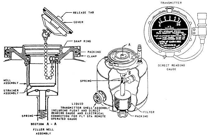
Nonpressurized Reservoirs Nonpressurized reservoirs are used in several transport, patrol, and utility aircraft. These aircraft are not designed for violent maneuvers; in some cases, they do not fly at high altitudes. Those aircraft that incorporate nonpressurized reservoirs and fly at high altitudes have the reservoirs installed within a pressurized area. High altitude in this situation means an altitude where atmospheric pressure is inadequate to maintain sufficient flow of fluid to the hydraulic pumps. Most nonpressurized reservoirs are constructed in a cylindrical shape. The outer housing is manufactured from a strong corrosion-resistant metal. Filter elements are normally installed internality within the reservoir to clean returning system hydraulic fluid. In some of the older aircraft, a filter bypass valve is incorporated to allow fluid to bypass the filter in the event the filter becomes clogged. Reservoirs serviced by pouring fluid directly into the reservoir have a filler strainer (finger strainer) assembly incorporated within the filler well to strain out impurities as the fluid enters the reservoir. Generally, reservoirs described in the above paragraph use a visual gauge to indicate the fluid quantity. Gauges incorporated on or in the reservoir may be either a glass tube, a direct reading gauge, or a float-type rod, which is visible through a transparent dome. In some cases, the fluid quantity may also be read in the cockpit through the use of quantity transmitters. A typical nonpressurized reservoir is shown in figure 7-4, This reservoir consists of a welded body and cover assembly clamped together. Gaskets are incorporated to seal against leakage between assemblies. QUANTITY INDICATING GAUGE. The reservoir fluid quantity is indicated through a mechanically operated float and arm (liquidometer) type of unit. The quantity gauge is mounted directly on the side of the reservoir. As shown in figure 7-4, the float and arm unit extends into the reservoir. The shell of the liquidometer provides a glass window over a pointer and dial, with the pointer mechanically linked to the float arm. As the float arm moves to correspond to the fluid level, the pointer, through mechanical linkage, moves to indicate the quantity available. This provides a direct reading sight gauge at the reservoir. This same float movement actuates the potentiometer wiper arm of an integral transmitter potentiometer. The remote indicating circuit is energized, and a duplicate indication of the reservoir
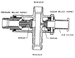
Figure 7-5.Pressure and vacuum relief valve. fluid quantity may be seen in the cockpit on a remote gauge. RESERVOIR PRESSURE AND VACUUM RELIEF VALVE. Although the reservoir shown in figure 7-4 is classified as a nonpressurized type, it has a sufficient amount of pressurization to ensure a
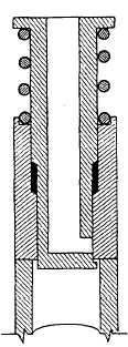
Figure 7-6.Manual air bleed valve. positive flow of fluid to the pump suction ports. The pressurization is derived from thermal expansion of fluid and the return of fluid to the reservoir from the main system. Most reservoirs of this type are vented directly to the atmosphere or cabin with only a check valve and filter to control the outside air source. The reservoir system includes a pressure and vacuum relief valve. The valve, as shown in figure 7-5, has two reservoir ports, and it is connected between and serves both main system reservoirs. The purpose of the valve is to maintain a differential pressure range between the reservoir and cabin. |
 
|
|
|
|
|
Integrated Publishing, Inc. - A (SDVOSB) Service Disabled Veteran Owned Small Business
|