Custom Search
|
|
  |
|
|
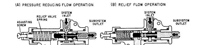
PRESSURE-REDUCING VALVES Pressure-reducing valves are used in hydraulic systems where it is necessary to lower the normal system operating pressure a specified amount. Figure 8-17 shows the operation of a pressure-reducing valve. View A of figure 8-17 shows system pressure being ported to a subsystem
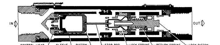
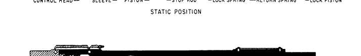
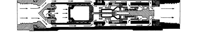
HYDRAULIC FUSES A hydraulic fuse is a safety device. Fuses may be installed at strategic locations throughout a hydraulic system. They are designed to detect line or gauge rupture, fitting failure, or other leak-producing failure or damage. One type of fuse, referred to as the automatic resetting type, is designed to allow a certain volume of fluid per minute to pass through it. If the volume passing through the fuse becomes excessive, the fuse will close and shut off the flow. When the pressure is removed from the pressure supply side of the fuse, it will automatically reset itself to the open position. Fuses are usually cylindrical in shape, with an inlet and outlet port at opposite ends, as shown in figure 8-18. A stationary sleeve assembly is con-tained within the body. Other parts contained within the body, starting at the inlet port, are a control head, piston and piston subassembly stop rod, a lock spring, and a lock piston and return spring. Fluid entering the fuse is divided into two flow paths by the control head. The main flow is between the sleeve and body, and a secondary flow is to the piston. Fluid flowing through the main path exerts a force on the lock piston, causing it to move away from the direction of flow, This movement uncovers ports, allowing fluid to flow through the fuse. The movement of the locking piston also causes a lock spring to release the piston subassembly stop
Any interruption of the flow of fluid through the fuse removes the operating force from the lock piston. This allows the lock piston spring to return the piston to the original position, which resets the fuse. RECOMMENDED READING LIST NOTE: Although the following reference was current when this TRAMAN was published, continued currency cannot be assured. You therefore need to ensure that you are studying the latest revision. Fluid Power, NAVEDTRA 12964, Naval Education and Training Program Management Support Activity, Pensacola, Florida, July 1990, Chapter 10. |
 
|
|
|
|
|
Integrated Publishing, Inc. - A (SDVOSB) Service Disabled Veteran Owned Small Business
|