Custom Search
|
|
  |
|
|
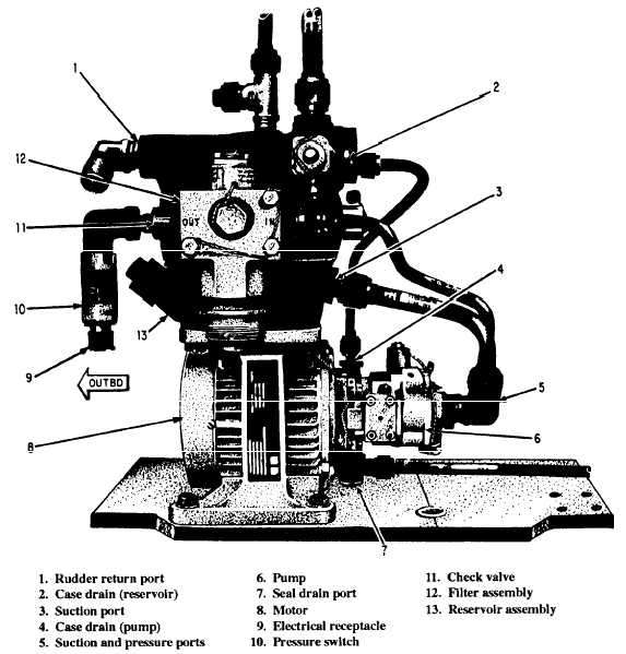
BACKUP SYSTEM Despite the dual system design requirement for flight control systems, a complete hydraulic system failure is possible. System failure could be a result of component or plumbing failure or as a result of enemy-inflicted damage. The backup flight control system, shown in figure 9-17, provides for an additional measure of flight control safety. The system activates whenever a partial or complete hydraulic system failure occurs. The complete backup flight control system is mounted on a protective armor plating that measures only 8 by 16 inches and is located close to the rudder and stabilizer power packages. Flight and combined
hydraulic system pressure line switches control the operation of this system. The two switches in the pressure lines to the backup flight system are wired normally closed at zero pressure. The backup pump outlet pressure switch is wired to normally open at zero pressure. The switches actuate at 900-1,100 psi on rising pressure and 700-900 psi on decreasing pressure. Closing of the combined or flight system pressure switches energizes the backup system motor pump. Closing the outlet pressure switch lights the backup hydraulic system indicator light on the annunciator panel in the cockpit. When pressure in the flight and/or combined hydraulic system decreases to 700-900 psi, the system is automatically activated. The system isolates a portion of the combined system in the tail of the aircraft by check valves in the pressure lines and a shutoff valve in the return line. When the shutoff valve closes, it stores a full charge of fluid in the backup system reservoir, The reservoir mounts on top of the motor-pump assembly. It has a capacity of 0.84 quarts. The return system shutoff valve is an integral part of the reservoir end flange inside the reservoir pressurizing spring. The soft-seated, poppet-type shutoff valve is held open when the reservoir is at the full position. When pressure drops and the reservoir piston moves about three-sixteenths of an inch away from the full position, the spring-loaded valve closes and prevents flow from the reservoir. The shutoff valve also acts independently as a relief valve to relieve reservoir pressure above 95 psi. Return fluid flow from the rudder and stabilizer actuators fills the backup system reservoir. When the reservoir approaches the full position, it mechanically opens a shutoff valve, allowing return flow to go to the combined system reservoir. In normal flight, the 40-psi return system pressure is enough to maintain the backup reservoir piston at the full position. The shutoff valve fully opens against its spring pressure. If return system pressure drops below the reservoir pressurizing spring pressure of 15 psi, the reservoir piston moves and displaces fluid through the shutoff valve. As the piston moves, the shutoff valve closes fully in three-sixteenths of an inch of piston movement. The shutoff valve may open momentarily during backup system operation to discharge excess fluid volume. This action may be a result of unequal stabilizer in-and-out stroke volume or thermal expansion of the fluid. The shutoff valve also opens when the flow rate exceeds the flow capacity of the backup pump. The latter condition could occur when the flight system is operating normally and high rate inputs are applied to the actuators. Pressure line isolation is accomplished by the use of check valves. To prevent backup system leakage to a failed combined system, a soft-seat check valve is installed upstream of the standard metal-seat check valve. These valves are found in the combined system pressure line. A three-position backup system hydraulic test switch is located in the cockpit. The central spring-loaded OFF position provides automatic function in flight. The momentary hold positions, COMBINED and FLIGHT, are for a ground test of the system when the aircraft is on external electrical power. Selection of either position will energize the motor pump when aircraft pressure is less than 700-900 psi. A cartridge-type filter element housed within the reservoir head and a pressure line filter protects the system from contamination. Since the backup motor pump is energized when either or both primary systems fail, the following three operational conditions can exist: 1. With the backup and flight systems operating, normal flight control is available. The backup system performs as an isolated system with the return shutoff valve closed. The variable displacement backup motor pump has a maximum rated output of 3 gpm at 1,000-psi output pressure to zero gpm at cutoff pressure (3,000-3,200 psi). The pump cannot match the high rate capacity of the flight system. Backup motor pump pressure will drop to zero when demand exceeds 3 gpm. Zero pressure causes the cockpit indicator light to go out. When pressure increases to 900-1,000 psi, the light will come on again, indicating backup system operation. 2. With the backup system and combined system operating, normal flight control is available. The backup system is not isolated, as normal combined system pressure exists within pressure and return lines. The return shutoff valve remains open. Combined system pumps maintain high pressure at the rudder and stabilizer actuators. Flow demand on the backup pump is not excessive at high rates. The cockpit indicator light should remain on, indicating backup system operation. 3. When the flight and combined systems fail, the backup flight control system performs as an isolated system. Surface rates available at the rudder and stabilizers are reduced by the limited output of the backup pump. There is no flaperon actuator control. The cockpit indicator will flicker out if the pilot applies inputs to the controls that exceed the capacity of the pump. The cockpit RUDDER THROW light will also be illuminated, indicating that approximately 33 percent of normal rudder throw is available. |
 
|
|
|
|
|
Integrated Publishing, Inc. - A (SDVOSB) Service Disabled Veteran Owned Small Business
|