Custom Search
|
|
  |
|
|
CABLE
AND RIGID CONTROL SYSTEMS
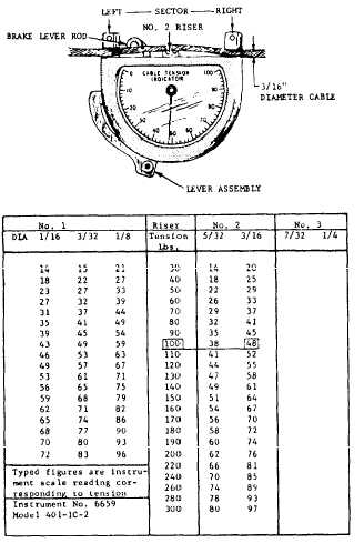
TROUBLESHOOTING When the cause and remedy for a reported malfunction in a control system are not immediately obvious to you, it maybe necessary to troubleshoot the system. Most aircraft MIMs provide troubleshooting charts that list some of the more common malfunctions in a system. Each discrepancy is accompanied by one or more probable causes, and a remedy is prescribed for each cause. The troubleshooting charts are organized in a definite sequence under each possible trouble, according to the probability of failure and ease of investigation. To obtain maximum value from these charts, they should be used systematically according to the aircraft manufacturers recommendations. Examples of typical troubleshooting charts and instructions on their proper use was discussed in chapter 3 of this TRAMAN. Since most aircraft use some form of electrical control or hydraulic boost in their flight control systems, maintenance of these systems must include the related electrical circuits and hydrauIic systems. Although an AE or AM is generally called upon to locate the correct electrical or hydraulic troubles respectively, you should be able to check circuits for loose connection, perform continuity checks, and perform minor troubleshooting of the hydraulic system. Basically there are seven distinct steps to follow during troubleshooting. These steps were discussed in chapter 3 of this TRAMAN. RIGGING AND ADJUSTING TOOLS The purpose of rigging and adjusting a primary flight control system is to ensure neutral alignment of all connecting components and to regulate and limit the surface deflection in both directions. Each aircraft has a set of special tools for flight control maintenance that may include rigging fixtures, pins, blocks, throwboards and protractors. Other common equipment, such as micrometers, pressure gauges, push-pull gauges, feeler gauges, tensiometer and calipers may also be required. These arc usually maintained in the toolroom and checked out when needed. Tensiometer The tensiometer is an instrument used in checking cable tension. Tension is the amount of pulling force applied to the cable. The amount of tension applied in a cable linkage system is controlled by turnbuckles in the system. A tensiometer is a precision cable tension measuring device, but it has limitations and can be awkward to use. It is inaccurate for cable tension under 30 pounds. When you take tension measurements, the instrument must not be pressed against any part of the aircraft, it cant be pushed or pulled against the cable, and the cable must not be pressed against fairleads or any part of the aircraft. Any one of these actions may lead to inaccurate measurements. A major advantage of cable linkage is its minimal space requirement and the ease in which it can be routed around, through, and behind aircraft structures and components. This can make access difficult and the tensiometer awkward or difficult to use. Adequate clearance for the tensiometer is necessary. All tensiometers must be certified by a calibration laboratory for accuracy at least once a month. One type of tensiometer is shown in figure 9-23. This instrument works on the principle of measuring
the amount of force required to deflect a cable a certain distance at right angles to its axis. The cable to be tested is placed under the two blocks on the instrument, and the lever assembly on the side of the instrument is pulled down. Movement of this lever pushes up on the center block, called a "riser." The riser pushes the cable at right angles to the two clamping points. The force required to do this is indicated by a pointer on the dial. Different risers are used with different size cables. Each riser carries an identifying number, and is easily inserted in the instrument. Each tensiometer is supplied with a calibration table to convert the dial readings into pounds. One of these calibration tables is shown in figure 9-23. For example, if the pointer on the dial indicates 48 with a No. 2 riser and a 3/16-inch diameter cable, the actual tension on the cable is 100 pounds. With this particular instrument, the No. 1 riser is used with 1/16-, 3/32-, and 1/8-inch diameter cables. CAUTION The calibration table applies to the particular instrument only, and cannot be used with any other. For this reason, the calibration table is secured inside the cover of the box in which the instrument is kept. The chart is serialized with the same serial number as the instrument. Using the cali-bration table from another instrument will result in inaccurate reading. During the adjustment of turnbuckles, the calibration table must be used to obtain the desired tension in a cable. For example, to obtain a tension of 110 pounds in a 3/16-inch diameter cable, the No. 2 riser is inserted in the instrument and the number opposite 110 pounds is read from the calibration table. In this case, the number is 52. The turnbuckle is then adjusted until the pointer indicates 52 on the dial. NOTE: Tensiometer readings should not be taken within 6 inches of any turnbuckle, end fitting, or quick disconnect. In some cases, the position of the tensiometer on the cable may be such that the face of the dial cannot be seen by the operator. In such cases, after the lever has been set and the pointer moved on the dial, the
The tensiometer, like any other measuring instru-ment, is a delicate piece of equipment and should be handled carefully. Tensiometers should never be stored in a toolbox. Temperature changes must be considered in cable-type systems since this will affect cable tensions. When a temperature is encountered that is lower than that at which the aircraft was rigged, the cables become slack because the aircraft structure contracts more than the cables. When temperatures higher than that at which the aircraft was rigged are encountered, the aircraft structure expands more than the cables and tension is increased. The cables in any cable linkage system are rigged according to a temperature chart that is contained in the applicable maintenance instructions manual. This chart will give the proper tensions for the various temperature changes above and below the temperature at which the system was rigged. |
 
|
|
|
|
|
Integrated Publishing, Inc. - A (SDVOSB) Service Disabled Veteran Owned Small Business
|