Custom Search
|
|
  |
|
|
CABLE AND RIGID CONTROL
SYSTEMS
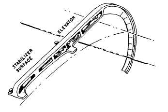
RIGGING In the elevator system shown in figure 9-26, rigging begins at the aft sector. The aircraft manufacturer has determined the position of the aft sector when it is in the neutral position. A rig pinhole has been furnished in the sector and a mating hole in the adjoining structure. See the three rig pins in figure 9-26. With the rig pin inserted in the aft sector and in the aircraft structure, the sector is held firmly in the neutral position. With the sector in this position, the push-pull tube connecting the sector with the elevator fitting assembly is adjusted to position the elevators to the neutral position. The neutral position is determined by using the elevator rigging fixture shown in figure 9-27. The curved section of the rigging fixture is graduated in degrees on either side of the neutral (zero degree) position that is about midway on the curved part of the fixture. The rigging fixture is fastened securely to the aircraft at the indicated points of attachment. When properly mounted, the index marks (graduations) on the curved section align with the elevators and indicate the position, in degrees, of the elevators. If, with the aft sector rig pin in place, the elevators are not in neutral (for example, 5 degrees above the neutral mark), lengthening the push-pull rod end will push the elevator fitting assembly forward, and thereby lower the elevators. If the elevators are too low, then shortening the rod will bring them up as required. The next step is the adjusting and tightening of the pair of cables in the system. This is accomplished by tightening the turnbuckles on each cable evenly until the required tension is obtained. During cable tightening, the rig pin is retained in the aft sector, leaving the forward sector free to turn. Therefore, when the necessary tension is recorded on one cable, that is also the tension on the other cable. To ensure that the cables were tightened evenly, check the forward sector rig pin hole to see if the rig pin can be inserted through the sector and into the structure. If this is not possible, then the cables must be adjusted by loosening one and tightening the other. This will maintain the correct tension on the cables, and, at the same time, rotate the forward sector to the neutral position. The cable section is properly rigged when it is possible to insert and remove the forward sector rig pin easily with the aft sector pin installed and the cables tightened to the prescribed tension. The push-pull rod connecting the forward sector and the bell crank is adjusted to the correct length by installing a rig pin in the bell crank. Then, the rod adjustable eye is turned in or out until the rod can be installed between the sector and bell crank without binding. At this point three rig pins are in place, and should remain in place until the control sticks are rigged to neutral. When you are positioning the control sticks to neutral, the rear stick must be adjusted first. Remember, we are working forward from the elevator surface. The push-pull rod connecting the bottom of the rear stick with the bell crank must be adjusted until the stick center line is the prescribed number of degrees forward of a vertical reference line. See the vertical reference line (14) and the center line (15) in figure 9-26. The vertical reference line is a position that the center line of the control stick would attain at a 90-degree angle (19) to the cockpit floor (20). Adjust the length of the push-pull tube between the control sticks to position the front control stick to an angle identical to that of the aft control stick. Then, remove all three rig pins. This completes the rigging and adjusting of the control system to neutral. All that remains is to adjust the stops that limit the fore and aft
travel of the control sticks, and rig and adjust the bungee that holds the system in the neutral position. The stop bolts (2) (fig. 9-26) are located in front and behind the aft control stick. They are installed so that the stick hits the stop bolts at the extreme limits of its travel. The maximum travel of the elevators in each direction is determined by the manufacturer and is controlled by the stop bolts. With the rigging fixture still in place, move the control stick all the way forward, and adjust the stop until the elevator DOWN throw conforms to the MIM. Pull the stick all the way aft, and adjust the aft stop bolt to obtain the correct elevator UP throw. The stop bolts are safety wired in place after this adjustment. The last item to be adjusted in this control system is the centering bungee. Connect the bungee and adjust its rod end so that with the stick against the stop bolt in the full down elevator position, the bungee is a minimum of 1/32 of an inch from bottoming. After this adjustment, the elevators should be held in neutral (plus or minus the prescribed number of degrees) by bungee action. If the elevators are too high, shorten the bungee rod end. If they are too low, lengthen the bungee. With the bungee properly adjusted, tighten the bungee rod end locknut and safety wire it. |
 
|
|
|
|
|
Integrated Publishing, Inc. - A (SDVOSB) Service Disabled Veteran Owned Small Business
|