Custom Search
|
|
  |
|
|
EMERGENCY FLAP SYSTEM If electrical and hydraulic power fails, the flaps can be lowered by the emergency system. An emergency flap extension bottle with a 300-cubic-inch capacity and charged to 3,000 psi provides a power source. Emergency extension is controlled by the emergency flap control handle, which is mechanically linked to the emergency flap air selector valve. Pulling the handle aft, the piston inside the air selector valve shifts, alIowing high-pressure air to flow through a separate set of lines to shuttle valves in the flap system. The shuttle valves reposition, and air pressure extends the flap actuators. Air pressure also repositions the flap system dump valve, dumping return side hydraulic
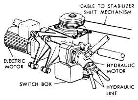
SEMI-INDEPENDENT FLAP AND SLAT SYSTEM This system consists of semi-independent flap and slat systems, which raise and lower using hydraulic motors drive units, torque tubes, and screw jack-type actuators. Flap System The flaps divide into two panels per wing at the wing-fold joint. Each panel is supported by two sets of tracks and rollers that are driven by two ball screw actuators. Pressure from the combined hydraulic system powers the flap drive motor and gearbox assembly, shown in figure 9-35. If the combined hydraulic system fails, a hydraulic brake locks the hydraulic motor, and an emergency electric motor provides continued operation. Emergency flap extension and retraction is controlled by placing the EMERG FLAP switch on the throttle quadrant at either UP or DN. Cam-operated switches within the flap drive gearbox provide input signals to show the flap position on the cockpit-integrated position indicator. Operation of the flap control handle energizes the solenoid-operated flap selector valve, directing hydraulic pressure to the extend or retract lines of the flap drive motor. The wings must be spread and locked to provide a complete electrical circuit through the wing unlock relay to the selector valve.
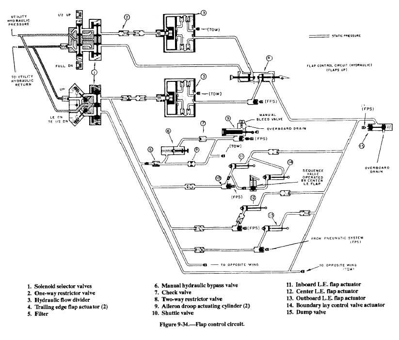
The flap actuators, shown in figure 9-34, drive the carriage and attaching flaps out and down to the 30-degree position. The limit switch in the flap drive gearbox opens, de-energizing the selector valve circuit, allowing the valve shuttle to return to neutral, blocking flow to the motor, and preventing further flap extension. Placing the flap control handle to LAND mechanically closes the 40-degree down flap handle switch. The electrical circuit to the selector valve completes, this time through the now closed 40-degree down limit switch in the flap drive gearbox. The flaps will extend to 40 degrees, and the electrical circuit will be broken by the action of the limit switch. Moving the flap control handle to the TAKEOFF or UP position will energize the opposite solenoid of the flap selector valve and port pressure to the retract side of the flap hydraulic motor. If the TAKEOFF position is selected, a limit switch will again halt flap movement at the 30-degree position. If UP is selected, retraction will be halted when the flaps reach the full up position. Stopping the flaps is a function of the flaps up limit switch. At the same time, linkage from the up limit switch actuates a second switch to complete the electrical circuit to the flap hydraulic motor brake valve. The energized valve blocks combined hydraulic system pressure that is holding the hydraulic brake in the unlocked position. The brake locks the hydraulic motor, which, in turn, locks the flaps in the up position. If combined hydraulic system pressure fails and the emergency flap switch is used, the flap action is powered by the electric motor. See figure 9-35. The flap hydraulic brake valve is energized, and the pressure holding the spring-loaded hydraulic motor brake unlocked will port to return. The brake is then free to lock the motor and input shaft. The electric motor now drives the flap gearbox and associated linkage, bypassing the locked hydraulic motor. This action occurs until the flaps reach a 40-degree trailing edge down position. Limit
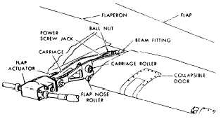
Figure 9-36.Flap actuator. switches shut the electric motor off when the flaps reach the 40-degree down and full up positions. |
 
|
|
|
|
|
Integrated Publishing, Inc. - A (SDVOSB) Service Disabled Veteran Owned Small Business
|