| Tweet |

Custom Search
|
|

  |
|
|
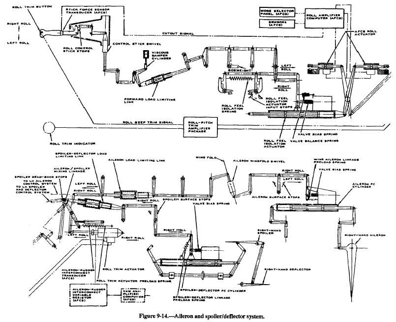
Combination Aileron/Spoiler Deflector System Navy aircraft employ more than one system for lateral control of the aircraft. Figure 9-14 shows an aileron and spoiler/deflector arrangement to achieve an increased roll rate about the longitudinal axis. In this system, left and right control stick movements transfer mechanically to the aileron and spoiler/deflector control linkage. The viscous damper cylinder is connected in the linkage. It resists rapid control stick movement, presenting overcontrol of the aileron system when the control augmentation mode of the AFCS is engaged. The control augmentation mode of the AFCS improves lateral and longitudinal stability of the aircraft. The load-limiting links located throughout the system protect control linkage and components from excessive loads These links have a breakout force, so they normally act as a fixed link. Loads that exceed the breakout force cause the links to extend or retract and absorb the overload. Artificial feel is provided by the mechanical feel spring assemb]y. The assembly simulates air load resistance at the control stick. When released, the control stick returns to neutral by the feel spring preload. The roll-feel isolation actuator prevents excessive forces from reaching the control stick. When the control stick is deflected, linkage to the feel isolation actuator servo valve repositions the servo valve slider and directs hydraulic pressure to the actuating pistons. The cylinder housing is connected to the control linkage and moves in the direction corresponding to stick movement. As the cylinder housing moves, the servo valve slider repositions to neutral, blocking fluid flow to and from the actuator until new inputs are initiated. The AFCS roll actuator connects to the control linkage by a scissor link. Normally, this scissor link acts as a simple idler. When the actuator receives signals from the AFCS, it causes, the linkage to act as a variable link. This action produces control system inputs completely independent of the control stick. Output motion from the AFCS linkage is transmitted through control system linkage to the aileron trim and mixing linkage. The mixing linkage directs inputs to both the aileron and spoiler/deflector linkage. Dead-band stops within the mixing linkage allow the ailerons to reach a trailing edge up position of 2 degrees 30 minutes, 15 minutes, before any spoiler/deflector motion is initiated. The power control cylinders for the ailerons and the spoiler/deflectors are tandem type. Power control No. 1 and power control No. 2 hydraulic systems supply hydraulic pressure. Half of the servo valve on each cylinder directs PC No. 1 hydraulic pressure to the corresponding half of the PC cylinder. The second half of the servo valve directs PC No. 2 hydraulic pressure to the other half of the cylinder. If one system fails, the other system operates the ailerons and spoiler/deflectors. Input control linkage connected to the servo valve control arm of the PC cylinders positions the valve slider to direct pressure to the actuating pistons. The actuating piston extends or retracts the cylinder housing. As the cylinder housing moves, the servo valve control arm repositions the servo valve slider. When the ailerons and spoiler/deflectors position is equal to the demand input, the servo valve slider is again at neutral. Fluid flow is blocked to and from the cylinder until a new control system input is initiated. The spoiler/deflector on each wing operates with the upward throw of the aileron on that wing. They are located in the left- and right-hand wing center sections, forward of the flaps. The spoiler extends upward into the airstream, disrupting the airflow and causing decreased lift on that wing. The deflector extends down into the airstream and scoops airflow over the wing surface aft of the spoiler, preventing airflow separation in that area. A stop bolt on the spoiler/deflector bell crank limits movement of the spoiler to 60 degrees of deflection. The deflector is mechanically slaved to the spoiler. It can be deflected to a maximum of 30 degrees when the spoiler is at 60 degrees. The spoiler deflectors open only with the upward movement of the ailerons. They are normally closed. The linkage motion lost when the aileron is down is absorbed by the spoiler deflector load-limiting link.
Spoiler Control System On one model aircraft, spoiler action is provided through the control stick grip, roll command transducer, roll computer, pitch computer, and eight spoiler actuators (one per spoiler). When used to increase the effect of roll-axis control, the spoilers can only be controlled when the wings are swept forward at 57 degrees. Right or left movement of the control stick grip mechanically transfers to the roll command transducer. The transducer converts the movement to inboard and outboard spoiler roll commands. Because the spoilers are vital for landing, the left- and right-wing inboard and No. 1 mid-spoilers are controlled by the roll computer. The spoilers are powered by the combined hydraulic power systems. The left and right outboard and No. 2 mid-spoilers are controlled by the pitch computer. These spoilers are powered by the mid-outboard spoiler/high lift backup module. This combination provides positive spoiler control if either computer or hydraulic power source malfunctions. |
 
|
|
|