Custom Search
|
|
  |
|
|
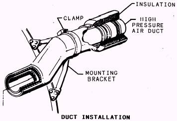
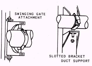
COMMON AIR-CONDITIONING COMPONENTS Some components and hardware are com-mon to all ACSs. Bleed-air ducting is manu-factured from stainless steel and can withstand pressures up to 450 psi and temperatures up to 800 F (425 C). These ducts are covered with high-temperature insulation (fig. 3-3) to protect aluminum structures and electrical lines near the ducting. Bellows assemblies are manufactured for two functions. The tolerance compensator (fig. 3-4) can be adjusted in length and allows for easier removal and replacement of the bleed- air duct. The thermal compensator (fig. 3-5) allows for thermal expansion throughout the bleed-air ducting. To support and brace the ducting, flexible mounting brackets are used (fig. 3-6). The use of these and other types of support brackets will vary with location and type of duct used. Air-conditioning distribution lines are manufactured from aluminum alloy and are subjected to relatively low pressures and temperatures.
Figure 3-3.- Bleed-air ducting.
Figure 3-4.- Tolerance compensator.
Figure 3-5.- Thermal compensator.
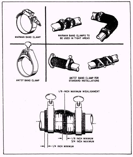
Figure 3-6.- Flexible mounting brackets. A variety of clamping devices are used in connecting aircraft environmental control system ducting sections to each other or to various components. Whenever lines, com-ponents, or ducting are disconnected or re-moved for any reason, install plugs, caps, or coverings on the openings to prevent the entry of foreign materials. Tag the various parts to ensure correct reinstallation. Care should be exercised during handling and installa-tion to ensure that flanges are not scratched, distorted, or deformed. Flange surfaces should be free of dirt, grease, and corrosion. The protective flange caps should be left on the ducting until the installation progresses to the point where removal is necessary to continue with the installation. In most cases it is mandatory to discard and replace seals and gaskets. Ensure that seals and gaskets are properly seated and that mating and alignment of flanges are fitted so that excessive torque is not required to close the joint and impose structural loads on the clamping device. Adjacent support clamps and brackets should remain loose until installation of the coupling has been completed. Marman type clamps commonly used in ducting systems should be tightened to the torque value indicated on the coupling. Tighten all couplings in the manner and to the torque value as specified on the clamp or in the applicable MIM. Some of the most commonly used plain band couplings (flexible line connectors) are illustrated in figure 3-7. When installing a hose between two
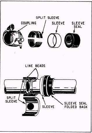
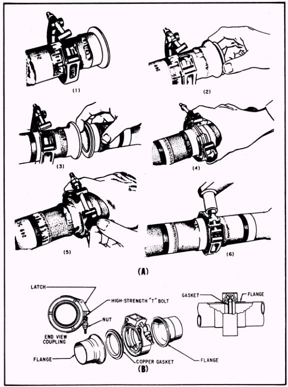
Figure 3-7.- Flexible line connectors. duct sections, as illustrated in figure 3-7, the gap between the duct ends should be 1/ 8 inch minimum to 3/ 4 inch maximum. When install-ing the clamps on the connection, the clamp should be 1/ 4 inch minimum from the end of the connector. Misalignment between the ducting ends should not exceed 1/ 8 inch maximum. When installing flexible line connectors, such as the one illustrated in figure 3-8, follow the steps listed below to assure proper installation and security: 1. Fold back half of the sleeve seal and slip it onto the sleeve. 2. Slide the sleeve (with the sleeve seal partially installed) onto the line. 3. Position the split sleeves over the line beads. 4. Slide the sleeve over the split sleeves and fold over the sleeve seal so that it covers the entire sleeve. 5. Install the coupling over the sleeve seal and torque to correct value. NOTE: Torque values for the various sizes and types of couplings maybe found by referring to the applicable MIM. Some couplings will have the correct torque value marked on the outside of the band. When installing rigid line couplings, follow the steps listed below and illustrated in fig-ure 3-9: 1. Slip the V-band coupling over the flanged tube. 2. Place a gasket into one flange. One quick rotary motion assures positive seating of the gasket. 3. Hold the gasket in place with one hand while the mating flanged tube is assembled into the gasket with a series of vertical and horizontal motions to assure the seating of the mating flange to the gasket. NOTE: View B of figure 3-9 illustrates the proper fitting and connecting of a rigid line coupling, using a metal gasket between the ducting flanges.
Figure 3-8.- Installation of flexible line connectors. 4. While holding the joint firmly with one hand, install the V-band coupling over the two flanges. 5. Press the coupling tightly around the flanges with one hand while engaging the latch. 6. Tighten the coupling firmly with a ratchet wrench. Tap the outer periphery of the coupling with a plastic mallet to assure proper alignment of the flanges in the coupling. This will seat the sealing edges of the flanges in the gasket. Tighten again, making sure the recommended torque is not exceeded. 7. Check the torque of the coupling with a torque wrench and tighten until the specified torque is obtained.
Figure 3-9.- Installation of rigid line couplings.
|
 
|
|
|