Custom Search
|
|
  |
|
|
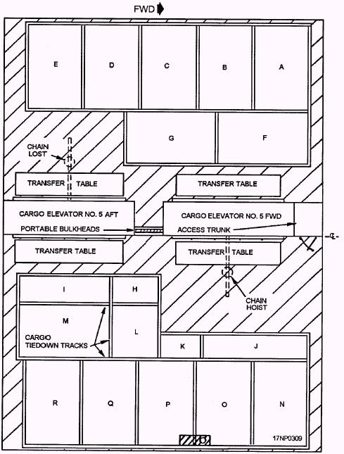
The internal arrangement of each magazine may vary considerably, The arrangement depends on the stowage space available (fig. 11-8) and the type of
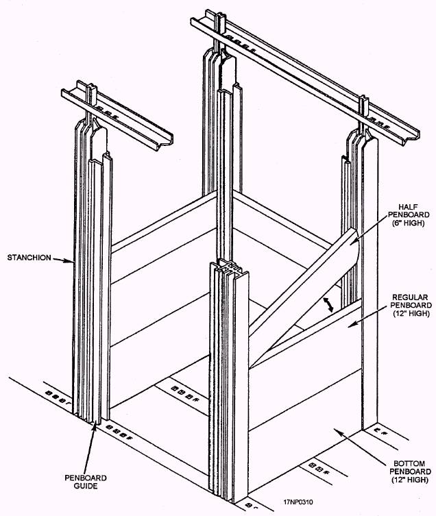
Figure 11-8.-Typical LFORM ammunition stowage plan for an LHA-1. ammunition stowed. Figure 11-5 shows a ready-service magazine configured for ready-service missiles. Notice some missiles are stowed in cradles attached to the bulkhead. Other missiles are loaded onto handling equipment and ready for immediate issue. In larger magazines, such as primary missile magazines, stanchions may be installed in sockets provided in the deck and overhead. Cradles are attached to the stanchions to stow a large number of decanned, ready-service missiles. Straps are used to secure the missiles in the cradles. Stanchions are also used to divide a large magazine area into smaller areas or bins (fig. 11-9) to hold various sizes of ammunition with a minimum loss of space. The stanchions are fitted with slots or have other means for receiving battens. The battens (which run horizontally) provide the walls that form the bin. No matter which stowage method is used, arrange the stowage area so access to as much ammunition and as many containers as possible is provided, and provide adequate space for ventilation and handling operations. Stow ammunition and explosives on dunnage to provide an air space so all parts of the magazine receive maximum ventilation and exposure to the sprinkler system. Mk 3 or Mk 12 metal pallets are used as dunnage aboard aircraft carriers. These have the correct space between the deck and stowed material. They also provide adequate grounding, Additionally, make sure that there is an air space of not less than 2 inches between any ammunition stowage stack and the surface of adjacent plating or sheathing. Stow the stacks of ammunition so sprinkler systems, circuit F sensors, or air escape lines aren't obstructed. When different lots and/or types of ammunition are stored in the same magazine, segregate the ammunition by lot, size, and type. Record this information on magazine cards and post them in the magazine. Ships at sea move randomly; therefore, securely fasten all hazardous munitions and explosives in place, except when they are actually being handled. In some cases, stanchions and battens provide adequate security. Other types of ammunition stows, such as palletized bombs or missile containers, are secured by tie-down chains especially designed for this purpose. Connect the tie-down chains to the load and the deck tie-down points so even the slightest movement of the ammunition is prevented. MAGAZINE INSPECTION AND VISUAL SURVEILLANCE OF AMMUNITION The terms magazine inspection and visual surveillance of ammunition mean the same thing. They apply to the inspection of magazines and their contents. Aboard ship, these inspections are mandatory according to The Ships' Maintenance and Material Management (3-M) Manual, OPNAVINST 4790.4, other Navy regulations, and NAVSEASYSCOM instructions. Magazine inspections are part of the ship's Preventive Maintenance System (PMS), and they should only be conducted by qualified personnel. These personnel use a check sheet (maintenance requirements card) to ensure that a hazard or abnormal condition is not overlooked. Generally, the daily visual inspection of magazines consists of checking for the following: Improperly secured stowage Unsatisfactory protective packaging Unusual fumes or odors Magazine cleanliness Other abnormal conditions Abnormal conditions in a ship's magazine or ammunition stowage space include evidence of tampering to gain access, evidence of theft, evidence of temperature or humidity fluctuations, and the presence of unauthorized materials. Abnormal conditions also include evidence of localized overheating from adjacent compartments on decks, bulkheads, and overheads; indications of leaks from sprinkler or flood pipes, nozzles, or control valves and regulators; and inoperable or damaged reach-rods, linkages, automatic fire alarm devices, and other similar equipment in the specific hazard stowages. Record the results of all magazine inspections on the appropriate PMS schedule. An important requirement of the daily magazine inspection is observing, recording, and reporting maximum and minimum temperature conditions in each stowage space. A maximum-minimum thermometer (one or more per magazine) is placed in all magazines when ammunition is stowed in them. The
Figure 11-9.-Typical stanchions and bin configuration. maximum-minimum thermometer (fig. 11-10) is a U-shaped, mercury-filled, glass tube with two bulbs. You determine the current temperature by the level of the mercury in either arm of the tube. The current temperature indicated by the thermometer shown in figure 11-10 is approximately 95F. The mercury level in each side of the tube should indicate the same temperature reading. If the readings are not the same on both sides of the tube, replace the thermometer. The maximum and minimum temperatures may be determined by observing the position of the steel index marker located in either side of the glass tube. If the temperature increases, the mercury rises upward in the right-hand scale, forcing the steel index marker upward, while the mercury in the left-hand scale decreases downward and the steel index marker remains stationary. If the temperature decreases, the mercury in the left-hand scale rises, forcing the steel index marker upward, while the mercury in the right-hand scale decreases downward and the steel index marker remains stationary. The maximum temperature indicated on the thermometer illustrated is approximately 100F. The reference point for taking all maximum and minimum readings is always from the bottom edge of the steel index marker. The minimum temperature indicated is approximately 45F. After recording the temperature readings on the magazine temperature card, zero the thermometer. You use a horseshoe-shaped magnet to zero the thermometer. Place the magnet against the glass and draw it downward so each steel index marker is drawn down to the level of mercury. |
 
|
|
|
|
|
Integrated Publishing, Inc. - A (SDVOSB) Service Disabled Veteran Owned Small Business
|