Custom Search
|
|
  |
|
|
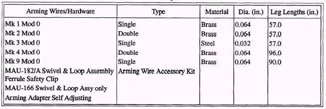
ARMING WIRE ASSEMBLIES Arming wire assemblies (fig. 1-24) are used for arming procedures during ordnance evolutions. The primary function of arming wire assemblies is to maintain ordnance components in a safe condition until actual release of the bomb from the aircraft. Normally, the wires consist of one or two brass or steel metal strands attached to a swivel loop. Safety Fahnstock clips (fig. 1-24) or safety clips, MAU 166/182, are attached to the ends of the arming wires after installation. They prevent premature or accidental withdrawal of the arming wires from the component. NOTE: Safety clips are used vice Fahnstock clips unless otherwise specified. Normally, arming wire assemblies are shipped in spiral-wound fiber tubes, overpacked in a wooden box. Generally, the safety Fahnstock clips are packed in the tubes with the arming wires. The most commonly used arming wire assemblies are listed in table 1-3. Arming wire installation procedures are discussed in the TRAMAN where the use of arming wire assemblies is required. FIN ASSEMBLIES Fin assemblies, used with the Mk 80 (series) LDGP bombs, provide stability to the bomb. They cause the bomb to fall in a smooth, definite curve to the target, instead of tumbling through the air. The fin assemblies, except the MAU-91A/B, are shipped on metal pallets. Each individual fin is crated Table 1-3.-Arming Wire Data
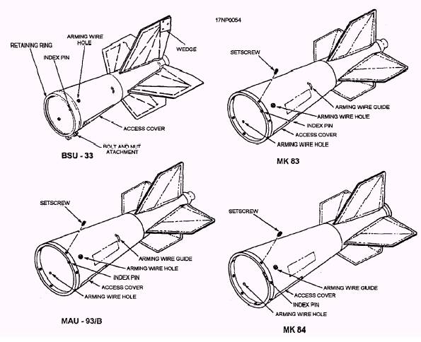
Figure 1-25.-Fin shipping configurations. 1-28 in a lightweight, disposable metal crate (fig. 1-25). Some fin assemblies are shipped with bomb lugs attached to the shipping crate, depending upon the particular Navy Ammunition Logistics Code (NALC). Two types of fins are described in this part of the TRAMAN-conical and Snakeye. The conical fin is used for the unretarded mode of delivery, and the Snakeye fin assembly can be used for either the unretarded or retarded mode of delivery. Conical Fin The typical BSU-33 conical fin assembly (fig. 1-26) is steel, conical in shape, and has four fins to provide stability. Access covers, attached by quick-release screws, are located on the sides of the fin body, providing access for dearming and inspections. There is a drilled or punched hole at the top and bottom of the forward end of the fin body. This hole is used to install an arming wire when the bomb is being configured for electric tail fuzing. The fin is attached to the aft end of the bomb, and is secured in place by tightening the fin setscrews into the V-groove of the bomb. The conical fin may be used with all Mk 80 (series) bombs. The basic difference between the types of conical fins is their physical size; the larger the bomb, the larger the fin. Snakeye Fin Assemblies Snakeye fin assemblies are used with the Mk 82 and Mk 83 LDGP bombs. They are capable of delivering bombs at high speed and low altitude without the danger of damaging the aircraft from ricocheting bombs or fragments, A physical description of both fin assemblies and the principles of operation are discussed in the following paragraphs. MK 15 AND MODS SNAKEYE FIN ASSEMBLY.- The Mk 15 and Mods bomb fin
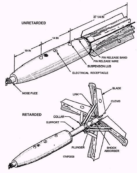
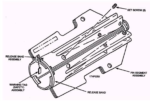
Figure 1-26.-Typical fin assemblies. 1-29 assembly (fig. 1-27) is a retarding fin. It is used with the 500-pound LDGP, Mk 82 and Mods bomb. The fin assembly presents a low-drag configuration when dropped in the unretarded position and a high-drag configuration when in the retarded position. The fin support tube is the main structure of the fin. It provides a means of attaching the fin assembly to the bomb. On Mod 4 and Mod 4A fins, the fin is attached by eight setscrews (fig. 1-28). On the Mod 4 and Mod 4A fins, the shock is absorbed by the crushing of a convoluted steel tube. The fin support tube has a fuze mounting ring for attaching the tail drive of a mechanical tail fuze The fins are spring-loaded and secured in the closed position by a spring-loaded release band. The release band lever (fig. 1-28) is prevented from opening by a cotter pin which stays installed until an arming wire is installed. The fin assemblies have drilled holes at the top and bottom of the forward end for installation of arming wires when the weapon is being configured for electric tail fuzing. MAU-91A/B FIN ASSEMBLY.- The MAU91A/B fin assembly (fig. 1-29) is a retarded tail fin used with the 1,000-pound LDGP bomb Mk 83 and Mods. This fin assembly can be dropped in either the retarded or unretarded position.
Figure l-27.-Mk 15 fin with Mk 82 bomb body. 1-30
Figure 1-28.-Fin release band for Mk 15 fin.
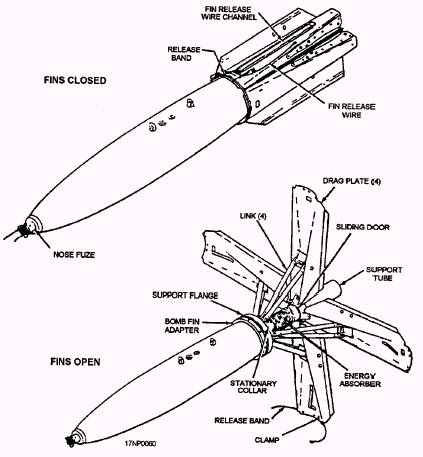
Figure 1-29.-Typica1 MAU-91A/B fin with ADU-320/B adapter on Mk 83 bomb body. The MAU-91 fin consists of four folding drag plates with links, a support flange, and a support tube. An energy absorber, made of aluminum honeycomb tubing, is located on the support tube between the stationary collar and the sliding collar. The sliding collar is driven against the energy absorber, causing it to compress and deform. A channel located on the top drag plate holds the fin release wire until it is pulled out at bomb release. The drag plates are held in the closed position by a release band that is secured by a fin release wire pin located in the latch of the release band. The band tabs fit into slots located near the end of each drag plate. The band is securely attached to the bottom drag plate by a stainless steel clamp, which prevents damage from the band striking the aircraft after release. The MAU-91 fin is attached to the Mk 83 bomb by fin adapter ADU-320/B. The adapter is secured to the aft end of the bomb by eight setscrews. The fin support flange has eight teeth that mate to ears on the fin adapter. A garter spring is forced into the gap between the flange teeth and the adapter, making sure that the teeth fit tightly against the ears. Two locking pins, which fit through matching holes in the flange and adapter, prevent rotation of the fin. The MAU-91 fin assembly is shipped in a wooden shipping and storage container. Included in the container are eight suspension lugs, one spare garter spring, and a spare locking pin. Principles of Operation There are three modes of delivery available for the Snakeye fin assembly. They are retarded, unretarded, and in-flight selection (pilot option) of either mode. RETARDED MODE.- In the retarded mode of delivery, the fins open to retard or slowdown the weapon. Since the aircraft and the weapon are traveling at the same speed when the weapon is released, the weapon and the aircraft arrive at the target at the same time. During low-level bombing, the aircraft could be damaged; therefore, the retarded mode of delivery is used during low-level bombing. The fin assembly is positively armed in the retarded configuration. In this configuration, the fin release arming wire is looped over a permanent structure on the bomb rack. As the weapon is released from the aircraft, the arming wire is pulled from the fin release band, and the spring-loaded fins pop open. The fins are forced to the full-open position by the airstream, which causes the weapon to rapidly decelerate and allows the releasing aircraft sufficient time to safely clear the target area. |
 
|
|
|