Custom Search
|
|
  |
|
|
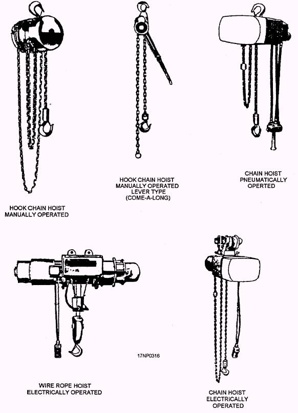
Aboard ship, most large magazine and weapons assembly areas are serviced by weapons elevators. These areas have provisions for the use of hoists. A brief description of handling equipment and its purpose is discussed in the following text. Hoists You use hoists in magazine stowage areas to stack or relocate ammunition within the magazine. You also use them to decan weapons. Hoists are used during weapons assembly to lift a weapon from the handling equipment or pallets to the assembly stands and from the assembly stand to the handling equipment. There are three basic types of hoists-manually powered, electrically powered, and pneumatically powered (fig. 11-14). A hoist maybe attached to the overhead by a stationary fitting, or it may be mounted onto an overhead monorail to move the load laterally. You must use the correct sling, hoisting beam, and bomb carrier when connecting the hoisting cable to the load. Hoists have an established safe working load (SWL) that you must consider when selecting a hoist for a particular job. Also, consider the SWL of the interfacing equipment (bomb carrier, sling, etc.). For example, you have selected a hoist with an SWL of 4,000 pounds and a bomb carrier with an SWL of 2,000 pounds. The maximum weight this configuration can safely lift is 2,000 pounds. Inspect hoists before you use them, Hoist must be periodically load tested. Equipment that has satisfactorily passed periodic load tests is marked to indicate its SWL. As a minimum, the marking includes the following information: The name of the testing activity and the name of the person performing the test. The date the test was performed The date of the next required inspection maybe included, if desired If the test period has expired or if documentation is not available to verify the latest load test status, the equipment is tested before it is used. If the equipment fails the load test specifications, the equipment is destroyed or, if economically feasible, repaired. Weapons Elevators There are currently more than 150 weapons elevators, involving over 55 different designs, installed on aircraft carriers. The size, type, and location of these weapons elevators will vary among the different classes of aircraft carriers. The Forrestal-class carriers, the USS Kitty Hawk, and USS Constellation have a combination of 5,500-pound, 2,000-pound, and 1,400-pound special armament stowage space (SASS) and improved weapons handling system (IWHS) elevators installed. The USS Enterprise and USS America were designed with pneumatically operated doors and hatches. The elevators on the USS America include five pneumatically operated elevators and three elevators that have hydraulically operated hatches and pneumatically operated doors. The USS John F. Kennedy was designed with platform conveyors and an athwartship shuttle. The elevators have hydraulically operated doors and hatches served from three power plants. Upper-stage elevators, numbers 2, 3, and 4, are raised and lowered by hydraulic ram instead of cables. The elevators aboard the USS Nimitz have two hydraulic power plants that serve 10 high-speed elevators. All the doors and hatches are hydraulically
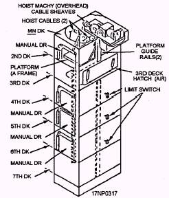
Figure 11-14.-Typical ammunition handling hoists. operated. In addition, all of the elevators are rated for a 9,000-pound load capacity, and the elevator trunks have side-loading capabilities at several magazine levels. Except for minor differences, the elevators aboard the USS Eisenhower and the USS Carl Vinson are almost identical to those aboard the USS Nimitz. The foIlowing text contains a brief description of the two major classifications (lower-stage and upper-stage) of weapons elevators. Regardless of the type of installation a weapons elevator provides a safe and efficient means for you to handle weapons and weapons components among the magazines and the various assembly, staging, and arming areas within the ship. LOWER-STAGE WEAPONS ELEVATORS (5,500 POUNDS).- The 5,500-pound, lower-stage, weapons elevator (fig. 11-15) services magazines and ammunition handling areas from the 7th-deck level up to and including the 2nd-deck level. The components of the elevator include an electrically powered, multiple-drum winch, an elevator platform, an enclosed, watertight, vertical trunk with doors located at the levels and stations serviced, and a semiautomatic control system. Ramps are used to bridge the gaps in the door opening between the elevator platform and the deck. These allow you to load or unload the elevator platform by using forklift trucks or wheeled skids.
Figure 11-15.-Typical 5,000-pound lower-stage, weapons elevator. Each lower-stage elevator is equipped with a broken-rope safety device, a down-speed governor device, and slack cable-sensing devices. The broken-rope safety device is mounted on the elevator platform assembly. If any one of the platform suspension ropes break, a roller-wedging mechanism automatically operates to lock the platform to the guide rails. A counterweight-type governor device for limiting speed of elevator down travel is located in the upper end of the elevator trunk. The governor is operated by a wire rope connected to a lever of the broken-rope safety device on the elevator platform. Then, the rope is passed over the governor sheave and attached to the governor spooling drum on the hoisting winch. Excessive down speed causes the governor limit switch to shutoff the power to the hoist motor and electric brake. Loss of electric power causes the brake to automatically stop the elevator. If the brake fails to stop the elevator, the governor sheave grips the governor rope, causing the broken-rope safety device to stop the elevator. A slack, cable-sensing, safety device is provided for each suspension rope and the governor rope. Located in the area between the winch drums and the overhead sheaves, these devices function by applying a spring-loaded follower roller to the wire rope. Rope slack causes a proximity switch to shutoff electrical power to the hoisting winch motor and brake, which stops the elevator. If the elevator overtravels upward beyond the maximum up stop position, an overtravel limit switch is actuated. This stops the elevator by shutting off power to the hoisting winch motor and brake. If the elevator overtravels downward beyond the hold deck loading station level, the platform is stopped by spring bumpers in the bottom of the elevator trunk. The slack-cable switches are actuated to cut off power to the hoisting winch motor and brake. An operator-attended control panel is located next to all elevator doors. All operator control panels have a display of selector switches, pushbuttons, and indicator lamps suited for the control functions required at the station served. All control panels have an emergency stop-run switch from which all operations of the elevator can be stopped. The main operator control panel and electrical power switch are located at the 2d deck-level station. An elevator can be dispatched to another level from any operator control panel. The lower-stage elevator control system can dispatch the elevator to another level. However, it can't retrieve the elevator from another level. |
|
|
|