Custom Search
|
|
  |
|
|
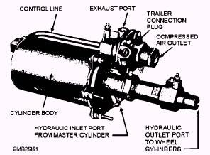
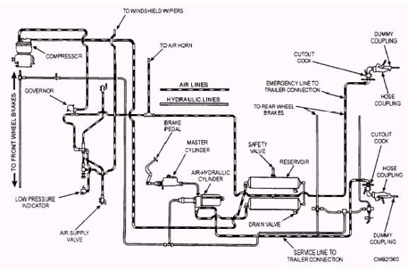
Learning Objective: Describe the operation, terms, and component functions of an air-over-hydraulic brake system. The air-over-hydraulic brake system is shown in figure 7-59. This system combines the use of compressed air and hydraulic pressure for brake application. Air pressure is supplied by a compressor and stored in reservoirs as with the air brake system. The master cylinder, wheel cylinders, and brake construction are very similar to that used in a hydraulic brake system. The essential difference between the straight hydraulic brake system and the air-over-hydraulic system lies in the AIR-HYDRAULIC-POWER CYLINDER. AIR-HYDRAULIC-POWER CYLINDER (AIR PAK) The air-hydraulic-power cylinder (fig. 7-60) is a self-contained power brake unit. The three essential components of the air-hydraulic-power cylinder are as follows: The COMPRESSED AIR CYLINDER consists of a large diameter air piston operating within a cylinder body. This piston actuates a pushrod, which is attached to the hydraulic piston within the slave cylinder.
Figure 7-60.- Air-hydraulic power cylinder assembly (Air-Pak). Movement of the piston in the compressed air cylinder is controlled by the amount of air, under pressure, that is allowed to enter through the control valve. The compressed air cylinder body is attached to the end plate on which the slave cylinder and control valve is
Figure 7-59.- Air-over-hydraulic brake system. The SLAVE CYLINDER consists of a cylindrical housing in which a small diameter hydraulic piston operates. The outlet cap houses a residual check valve and a ball-check valve is located in the hydraulic piston. The CONTROL VALVE consists of two poppets operating within a housing and actuated by a hydraulic relay piston and a reactionary-type diaphragm. An air control line connects the control valve to the compressed air cylinder. the relay piston in the control valve. As hydraulic pressure builds, the relay piston moves the control valve diaphragm forward, closing the atmospheric poppet and slightly opening the air pressure poppet. Air under pressure then passes through the air control line forcing the power piston in the air cylinder forward until the air pressure on the diaphragm, in combination with spring pressure, allows the air poppet to close. The degree of brake application is determined by the amount of compressed air trapped in the power cylinder when brake pedal movement is stopped. Unless more pressure is applied or the brake pedal is released, the brakes will remain in the partially applied position. |
 
|
|
|