Custom Search
|
|
  |
|
|
A circuit resistance test is used to locate faulty wiring, loose connections, partially burnt wire, corroded terminals, or other similar types of problems.
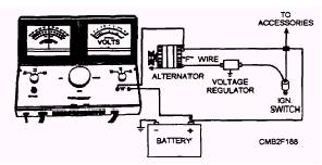
INSULATED RESISTANCE TEST.- To perform an insulated resistance test, connect the load tester as described by the manufacturer. A typical connection setup is shown in figure 2-35. Note how the voltmeter is connected across the alternator output terminal and positive battery terminal. With the vehicle running at a fast idle, rotate the load control knob to obtain a 20-amp current flow at 15 volts or less. All accessories and lights are to be turned OFF. Read the voltmeter. The voltmeter should NOT read over 0.7-volt drop (0.1 volt per electrical connection) for the circuit to be considered in good condition. However, if the voltage drop is over 0.7 volt, circuit resistance is high and a poor electrical connection exists. GROUND CIRCUIT RESISTANCE TEST.- With the ground circuit resistance test the voltmeter leads are placed across the negative battery terminal and alternator housing (fig. 2-36). The voltmeter should NOT read over 0.1 volt per electrical connection. If the reading is higher, this indicates such problems as loose or faulty connections, burnt plug sockets, or other similar malfunctions.
Figure 2-35.- Typical insulated resistance test setup.
Figure 2-36.- Typical ground circuit resistance test setup. |
 
|
|
|
|
|
Integrated Publishing, Inc. - A (SDVOSB) Service Disabled Veteran Owned Small Business
|