Custom Search
|
|
  |
|
|
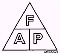
Learning Objective: Identify operational characteristics, component functions, and maintenance procedures of a hydraulic system. The extensive use of hydraulics to transmit power is due to the fact that a properly constructed hydraulic system possesses a number of favorable characteristics. These are as follows: Eliminates the need for complicated systems using gears, cams, and levers. Motion can be transmitted without the slack inherent in the use of solid machine parts. The fluids used are not subject to breakage as are mechanical parts. Hydraulic system mechanisms are not subjected to great wear. If the system is well-adapted to the work it is required to perform and not misused, it can provide smooth, flexible, uniform action without vibration and is unaffected by variation of load. Hydraulic systems can provide widely variable motions in both rotary and straight-line transmission of power. The need for control by hand can be minimized. In addition, they are economical to operate. BASIC PRINCIPLES OF HYDRAULICS Liquids have no shape of their own. Pressure and Force Computing Force, Pressure, and Area Force equals pressure times area. Thus, the formula is written F = P x A Pressure equals force divided by area. By rearranging the above formula, this state may be condensed into the following: P = F divided by A. Since area equals force divided by pressure, the formula for area is written as follows: A = F divided by P Figure 3-1 shows a memory device for recalling the different variations of the formula. Any letter in the triangle may be expressed as the product or quotient of the other two, depending on its position within the triangle. Incompressibility and Expansion of Liquids For all practical purposes, fluids are incom-pressible. Under extremely high pressures: the volume of a fluid can be decreased somewhat, though the decrease is so slight that it is considered to be negligible except by design engineers. Liquids expand and contract because of temperature changes. When liquid in a closed container is subjected to high temperatures, it expands and this exerts pressure on the walls of the container; therefore, it is necessary that pressure-relief mechanisms and expansion chambers be incorporated into hydraulic systems. Without these precautionary measures, the expanding fluid could exert enough pressure to rupture the system. Transmission of Forces through Liquids
Figure 3-1.- Device for determining the arrangement of the force, pressure, and area formula.
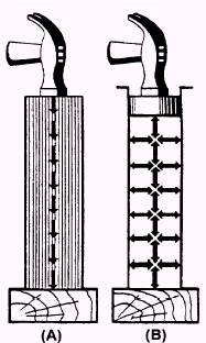
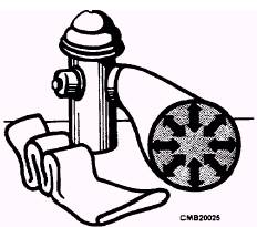
Figure 3-2.- Transmission of force: (A) Solid; (B) Fluid. When a force is applied to the end of a column of confined liquid (fig. 3-2, view B), it is transmitted straight through the other end and also undiminished in every direction throughout the column- forward, backward, and sideways- so that the containing vessel is literally tilled with pressure. An example of this distribution of force is shown in figure 3-3. The flat hose takes on a circular cross section when it is filled with water under pressure. The outward push of the water is equal in every direction. Pascal's Law
Figure 3-3.- Distribution of force. According to Pascal's law, any force applied to a confined fluid is transmitted in all directions throughout the fluid regardless of the shape of the container. Consider the effect of this in the systems shown in views A and B of figure 3-4. If there is resistance on the output piston (view A, piston 2) and the input piston is pushed downward, a pressure is created through the fluid which acts equally at right angles to surfaces in all parts of the container. If the force 1 is 100 pounds and the area of input piston 1 is 10 square inches, then pressure in the fluid is 10 psi ( 100 10). It must be emphasized that this fluid pressure cannot be created without resistance to flow, which, in this case, is provided by the 100-pound force acting against the top of the output piston 2. This pressure acts on piston 2, so for each square inch of its area, it is pushed upward with the force of 10 pounds. In this case, a fluid column of a uniform cross section is considered so the area of output piston 2 is the same as input piston 1, or 10 square inches; therefore, the upward force on output piston 2 is 100 pounds- the same as was applied to input piston 1. All that has been accomplished in this system was to transmit the 100- pound force around a bend; however, this principle underlies practically all-mechanical applications of fluid power. At this point, it should be noted that since Pascal's law is independent of the shape of the container, it is not necessary that the' tubing connecting the two pistons should be the full area of the pistons. A connection of any size, shape, or length will do so long as an unobstructed passage is provided. Therefore, the system shown in view B of figure 3-4 (a relatively small, bent pipe connects the two cylinders) will act the same as that shown in view A. |
 
|
|
|
|
|
Integrated Publishing, Inc. - A (SDVOSB) Service Disabled Veteran Owned Small Business
|