Custom Search
|
|
  |
|
|
An arrangement of interconnected components is required to transmit and control power through pressurized fluid. Such an arrangement is commonly referred to as a system. The number and arrangement of the components vary from system to system, depending on application. In many applications, one main system supplies power to several subsystems, which are commonly referred to as circuits. The complete system may be a small compact unit; more often, however, the components are located at widely separated points for convenient control. The basic components of a fluid power system are essentially the same, regardless of whether the system uses hydraulic or pneumatic medium. The basic components are as follows: Reservoir Reservoir 1. Dissipating heat from the fluid, Ideally, the reservoir should be high and narrow, rather than shallow and broad. The oil level should be as high as possible above the opening to the pump suction line. This condition prevents the vacuum at the line opening from causing a vortex or whirlpool effect. Anytime you see a whirlpool at the suction line opening, the system is taking in air. As a rule of thumb, the reservoir level should be two to three times the pump output per minute. By this rule which works well for stationary machinery, a 20- gpm system would require a 40-or 60-gpm reservoir. However, this is not possible for mobile equipment. You are more likely to find a 20-or 30-gallon tank to support a 100-gpm system. This is possible because mobile systems operate intermittently, rather than all the time. The largest reservoirs are on mobile equipment. These reservoirs may have a 40-or 50- gallon capacity, capable of handling more than 200- gpm output. The reservoir must be sized to ensure there is a reserve of oil with all the cylinders in the system fully extended. The reserve must be high enough to prevent a whirlpool at the suction line opening. Also, there
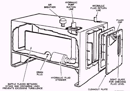
Figure 3-6.- Typical hydraulic reservoir. An air vent allows the air to be drawn in and pushed out of the reservoir by the ever-changing fluid level. An air filter is attached to the air vent to prevent drawing atmospheric dust into the system by the ever-changing fluid level. A firmly secured filling strainer of fine mesh wire is always placed below the filler cap. The sight gauge is provided so the normal fluid level can always be seen, as it is essential that the fluid in the reservoir be at the correct level. The baffle plate segregates the outlet fluid from the inlet fluid. Although not a total segregation, it does allow time to dissipate the air bubbles, lessen the fluid turbulence (contaminants settle out of nonturbulent fluid), and cool the return fluid somewhat before it is picked up by the pump. Reservoirs used on CESE may vary considerably from that shown in figure 3-6; however, manufacturers retain many of the noted features as possible depending on design limits and use. Strainers and Filters The most common device installed in hydraulic systems to prevent foreign particles and contamination from remaining in the system are called filters. They may be located in the reservoir, in the return line, in the pressure line, or any other location in the system where the designer of the system decides they are needed to safeguard the system against impurities. Filters are classified as full flow and partial flow. In the full-flow filter, all fluid that enters the unit passes through the filtering element, while in the partial-flow filter. only a portion of the fluid passes through the element. Pumps Pumps are rated according to their volumetric output and displacement. Volumetric output is the amount of fluid a pump can deliver to its outlet port in a certain period of time at a given speed. Volumetric output is usually expressed in gallons per minute (gpm). Since changes in pump speed affect volumetric output, some pumps are rated by their displacement. Pump displacement is the amount of fluid the pump can deliver per cycle. Since most pumps use a rotary drive, displacement is usually expressed in terms of cubic inches per revolution. Many different methods are used to classify pumps. Terms, such as nonpositive displacement, positive displacement, fixed displacement, variable displacement, fixed delivery, variable delivery, constant volume, and others are used to describe pumps. The first two of these terms describe the fundamental division of pumps because all pumps are either nonpositive displacement or positive displacement. Basically pumps that discharge liquid in a continuous flow are referred to as nonpositive displacement, and those that discharge volumes separated by a period of no discharge are referred to as positive displacement. Pumps may also be classified according to the specific design used to create the flow of fluid. Practically all-hydraulic pumps fall within three designs classifications- centrifugal, rotary, and reciprocating. Since the use of centrifugal pumps is limited, we will only discuss rotary and reciprocating. |
 
|
|
|
|
|
Integrated Publishing, Inc. - A (SDVOSB) Service Disabled Veteran Owned Small Business
|