POWER FLOW Constant mesh gears are seldom used for all speeds. Common practice is to use such gears for the higher gears, with sliding gears for FIRST and REVERSE, or for REVERSE only.
Now that you understand the basic parts and construction of a manual transmission, we will cover the flow of power through a five-speed synchromesh transmission. In this example neither first gear nor reverse gear are synchronized.
Reverse Gear Synchromesh Transmission
The construction of the synchromesh transmission is the same as that of the constant mesh transmission with the exception that a synchronizer has been added (fig. 4-19). The addition of synchronizers allows the gears to be constant mesh when the cluster gears and
In passing from neutral to reverse, the first-reverse main shaft gear is shifted rearward to mesh with the reverse idler gear (fig. 4-20, view A). The sole function of this gear is to make the main shaft rotate in the opposite direction to the input shaft; it does not affect gear ratio.

Figure 4-19.- Synchromesh transmission.
First Gear
To get the vehicle moving from a standstill, the operator moves the gearshift lever into first. The main shaft first-reverse speed gear is slid into position, meshing the gear with the countershaft first-speed gear. The countershaft first-speed gear and main shaft first-reverse speed gear transmits power to the main shaft (fig. 4-20, view B). Gear ratio is approximately 7.55 to 1.
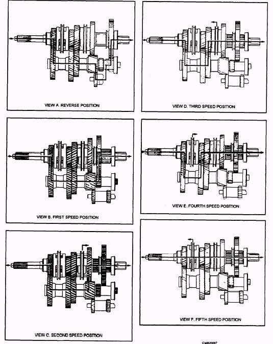
Figure 4-20.- Power flow of a five-speed transmission.
Second Gear
To shift into second, the operator depresses the clutch and moves the shift lever into second gear. The second-third-speed synchronizer has been moved to the right so its internal teeth engage the external teeth of the main shaft second-speed gear. Power is transmitted by the countershaft second-speed gear to the main shaft second-speed gear, which is coupled to the main shaft by the second-third-gear synchronizer, and to the main shaft (fig. 4-20, view C). Gear ratio is approximately 4.18 to 1.
Third Gear
To shift into third, the operator depresses the clutch and moves the shift lever disengaging the second-third synchronizer from the main shaft second-speed gear. The second-third-speed synchronizer has been moved to the left so its internal teeth engage the external teeth of the main shaft third-speed gear. Power is transmitted by the countershaft third-speed gear to the main shaft third-speed gear, which is coupled to the main shaft by the second-third synchronizer and through the main shaft (fig. 4-20, view D). Gear ratio is approximately 2.45 to 1.
Fourth Gear
The operator depresses the clutch and moves the shift lever disengaging the second-third synchronizer from the main shaft third-speed gear. The fourth-fifth- speed synchronizer has been moved to the right so its internal teeth engage the external teeth of the main shaft fourth-speed gear. Power is transmitted by the countershaft fourth-speed gear through the main shaft fourth-speed gear, which is coupled to the main shaft by the fourth-fifth-speed synchronizer, and through the main shaft (fig. 4-20, view E). Gear ratio is approximately 1.45 to 1.
Fifth Gear
The operator depresses the clutch and moves the shift lever disengaging the fourth-fifth-speed synchronizer from the main shaft fourth-speed gear. The fourth-fifth-speed synchronizer is moved to the left so its internal teeth engage the external teeth of the input gear. Power is transmitted by the input gear, which is coupled to the main shaft by the fourth-fifth-speed synchronizer. Since the interlocking action of the synchronizer, in effect, makes one continuous shaft of the input shaft and the main shaft, the drive is direct (fig. 4-20, view F). Gear ratio is 1.00 to 1.


