 |
||
|
|
||
| |||||||||||||||
|
|
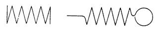
HELICAL SPRINGS There are three classifications of helical springs: compression, extension, and torsion. Drawings seldom show a true presentation of the helical shape; instead, they usually show springs with straight lines. Figure 4-15 shows several methods of spring representation including both helical and straight-line drawings. Also, springs are sometimes shown as single-line drawings as in figure 4-16. The military standards for finish marks are set forth in ANSI 46.1-1962. Many metal surfaces must be finished with machine tools for various reasons. The acceptable roughness of a surface depends upon how the
Figure 4-15.-Representation of commm types of helical springs.
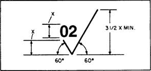
Figure 4-16.-Single line representation of springs part will be used. Sometimes only certain surfaces of a part need to be finished while others are not. A modified symbol (check mark) with a number or numbers above it is used to show these surfaces and to specify the degree of finish. The proportions of the surface roughness symbol are shown in figure 4-17. On small drawings the symbol is proportionately smaller. The number in the angle of the check mark, in this case 02, tells the machinist what degree of finish the surface should have. This number is the root-mean-square value of the surface roughness height in millionths of an inch. In other words, it is a measurement of the depth of the scratches made by the machining or abrading process. Wherever possible, the surface roughness symbol is drawn touching the line representing the surface to
Figure 4-17.-Proportions for a basic finish symbol.
which it refers. If space is limited, the symbol may be placed on an extension line on that surface or on the tail of a leader with an arrow touching that surface as shown in figure 4-18. When a part is to be finished to the same roughness all over, a note on the drawing will include the direction "finish all over" along the finish mark and the proper number. An example is FINISH ALL OVER3Z When a part is to be finished all over but a few surfaces vary in roughness, the surface roughness symbol number or numbers are applied to the lines representing these surfaces and a note on the drawing will include the surface roughness symbol for the rest of the surfaces. For example, ALL OVER EXCEPT AS NOTED (fig. 4-19).
Figure 4-18.-Methods of placing surface roughness symbols. |
|
Privacy Statement - Press Release - Copyright Information. - Contact Us - Support Integrated Publishing |