 |
||
|
|
||
| |||||||||||||||
|
|
CHAPTER 5 PIPING SYSTEMS When you have read and understood this chapter, you should be able to answer the following learning objectives: Interpret piping blueprints. Identify shipboard hydraulic and plumbing blueprints. PIPING DRAWINGS Water was at one time the only important fluid that was moved from one point to another in pipes. Today almost every conceivable fluid is handled in pipes during its production, processing, transportation, and use. The age of atomic energy and rocket power has added fluids such as liquid metals, oxygen, and nitrogen to the list of more common fluids such as oil,
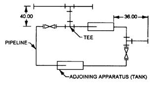
Figure 5-1.-Single-line orthographic pipe drawing. water, gases, and acids that are being carried in piping systems today. Piping is also used as a structural element in columns and handrails. For these reasons, drafters and engineers should become familiar with pipe drawings. Piping drawings show the size and location of pipes, fittings, and valves. A set of symbols has been developed to identify these features on drawings. We will show and explain the symbols later in this chapter. Two methods of projection used in pipe drawings are orthographic and isometric (pictorial). Chapter 3 has a general description of these methods and the following paragraphs explain their use in pipe drawings. Single- and double-line orthographic pipe drawings (fig. 5-1 and 5-2) are recommended for showing single pipes either straight or bent in one plane only. This method also may be used for more complicated piping systems. ISOMETRIC (PICTORIAL) PIPE DRAWINGS Pictorial projection is used for all pipes bent in more than one plane, and for assembly and layout work. The finished drawing is easier to understand in the pictorial format.
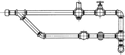
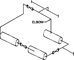
Figure 5-2.-Double-line orthographic pipe drawing. Draftsmen use single-line drawings to show the arrangement of pipes and fittings. Figure 5-3 is a single-line (isometric) pictorial drawing of figure 5-1. The center line of the pipe is drawn as a thick line to which the valve symbols are added. Single-line drawings take less time and show all information required to lay out and produce a piping system. Double-line pipe drawings (fig. 5-4) require more time to draw and therefore are not recommended for production drawings. Figure 5-4 is an example of a
Figure 5-3.-Single-line pictorial piping drawing of figure 5-1. double-line pictorial pipe drawing. They are generally used for catalogs and similar applications where visual appearance is more important than drawing time. |
|
Privacy Statement - Press Release - Copyright Information. - Contact Us - Support Integrated Publishing |