 |
||
|
|
||
| |||||||||||||||
|
|
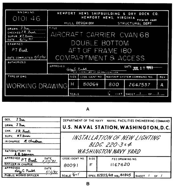
INFORMATION BLOCKS The draftsman uses information blocks to give the reader additional information about materials, specifications, and so forth that are not shown in the blueprint or that may need additional explanation. The draftsman may leave some blocks blank if the information in that block is not needed. The following paragraphs contain examples of information blocks. Title Block The title block is located in the lower-right corner of all blueprints and drawings prepared according to MIL-STDs. It contains the drawing number, name of the part or assembly that it represents, and all information required to identify the part or assembly. It also includes the name and address of the govemment agency or organization preparing the drawing,
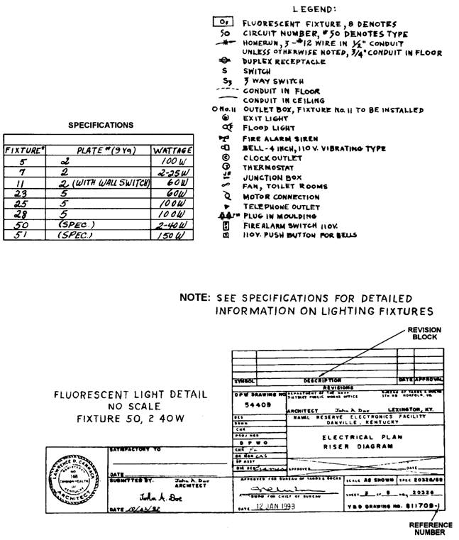
Figure 1-1.-Blueprint title blocks. (A) Naval Ship Systems Command; (B) Naval Facilities Engineering Command. the scale, drafting record, authentication, and date (fig. 1-1). A space within the title block with a diagonal or slant line drawn across it shows that the information is not required or is given elsewhere on the drawing. Revision Block If a revision has been made, the revision block will be in the upper right corner of the blueprint, as shown in figure 1-2. All revisions in this block are identified
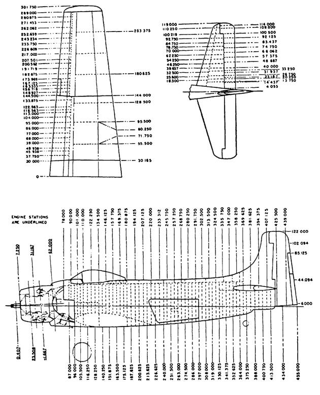
Figure 1-2.-Electrical plan. by a letter and a brief description of the revision. A revised drawing is shown by the addition of a letter to the original number, as in figure 1-1, view A. When the print is revised, the letter A in the revision block is replaced by the letter B and so forth. Drawing Number Each blueprint has a drawing number (fig. 1-1, views A and B), which appears in a block in the lower right corner of the title block. The drawing number can be shown in other places, for example, near the top border line in the upper corner, or on the reverse side at the other end so it will be visible when the drawing is rolled. On blueprints with more than one sheet, the information in the number block shows the sheet number and the number of sheets in the series. For example, note that the title blocks shown in figure 1-1, show sheet 1 of 1. Reference Number Reference numbers that appear in the title block refer to numbers of other blueprints. A dash and a number show that more than one detail is shown on a drawing. When two parts are shown in one detail drawing, the print will have the drawing number plus a dash and an individual number. An example is the number 811709-1 in the lower right corner of figure 1-2. In addition to appearing in the title block, the dash and number may appear on the face of the drawings near the parts they identify. Some commercial prints use a leader line to show the drawing and dash number of the part. Others use a circle 3/8 inch in diameter around the dash number, and carry a leader line to the part. A dash and number identify changed or improved parts and right-hand and left-hand parts. Many aircraft parts on the left-hand side of an aircraft are mirror images of the corresponding parts on the right-hand side. The left-hand part is usually shown in the drawing. On some prints you may see a notation above the title block such as "159674 LH shown; 159674-1 RH opposite." Both parts carry the same number. LH means left hand, and RH means right hand. Some companies use odd numbers for right-hand parts and even numbers for left-hand parts. Zone Number Zone numbers serve the same purpose as the numbers and letters printed on borders of maps to help you locate a particular point or part. To find a point or part, you should mentally draw horizontal and vertical lines from these letters and numerals. These lines will intersect at the point or part you are looking for. You will use practically the same system to help you locate parts, sections, and views on large blueprinted objects (for example, assembly drawings of aircraft). Parts numbered in the title block are found by looking up the numbers in squares along the lower border. Read zone numbers from right to left. Scale Block The scale block in the title block of the blueprint shows the size of the drawing compared with the actual size of the part. The scale may be shown as 1" = 2", 1" = 12", 1/2" = 1', and so forth. It also may be shown as full size, one-half size, one-fourth size, and so forth. See the examples in figure 1-1, views A and B. If the scale is shown as 1" = 2", each line on the print is shown one-half its actual length. If a scale is shown as 3" = 1", each line on the print is three times its actual length. The scale is chosen to fit the object being drawn and space available on a sheet of drawing paper. Never measure a drawing; use dimensions. The print may have been reduced in size from the original drawing. Or, you might not take the scale of the drawing into consideration. Paper stretches and shrinks as the humidity changes. Read the dimensions on the drawing; they always remain the same. Graphical scales on maps and plot plans show the number of feet or miles represented by an inch. A fraction such as 1/500 means that one unit on the map is equal to 500 like units on the ground. A large scale map has a scale of 1" = 10'; a map with a scale of 1" = 1000' is a small scale map. The following chapters of this manual have more information on the different types of scales used in technical drawings. Station Number A station on an aircraft may be described as a rib (fig. 1-3). Aircraft drawings use various systems of station markings. For example, the centerline of the
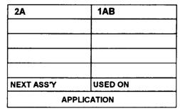
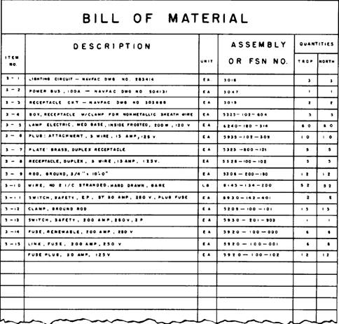
Figure 1-3.-Aircraft stations and frames. aircraft on one drawing may be taken as the zero station. Objects to the right or left of center along the wings or stabilizers are found by giving the number of inches between them and the centerline zero station. On other drawings, the zero station may be at the nose of the fuselage, at a firewall, or at some other location depending on the purpose of the drawing. Figure 1-3 shows station numbers for a typical aircraft. Bill of Material The bill of material block contains a list of the parts and/or material needed for the project. The block identifies parts and materials by stock number or other appropriate number, and lists the quantities requited. The bill of material often contains a list of standard parts, known as a parts list or schedule. Figure 1-4 shows a bill of material for an electrical plan. Application Block The application block on a blueprint of a part or assembly (fig. 1-5) identifies directly or by reference the larger unit that contains the part or assembly on the drawing. The NEXT ASS'Y (next assembly) column will contain the drawing number or model
Figure 1-5.-Application block.
Figure 1-4.-Bill of material. number of the next larger assembly of which the smaller unit or assembly is a part. The USED ON column shows the model number or equivalent designation of the assembled units part. |
|
Privacy Statement - Press Release - Copyright Information. - Contact Us - Support Integrated Publishing |