 |
||
|
|
||
| |||||||||||||||
|
|
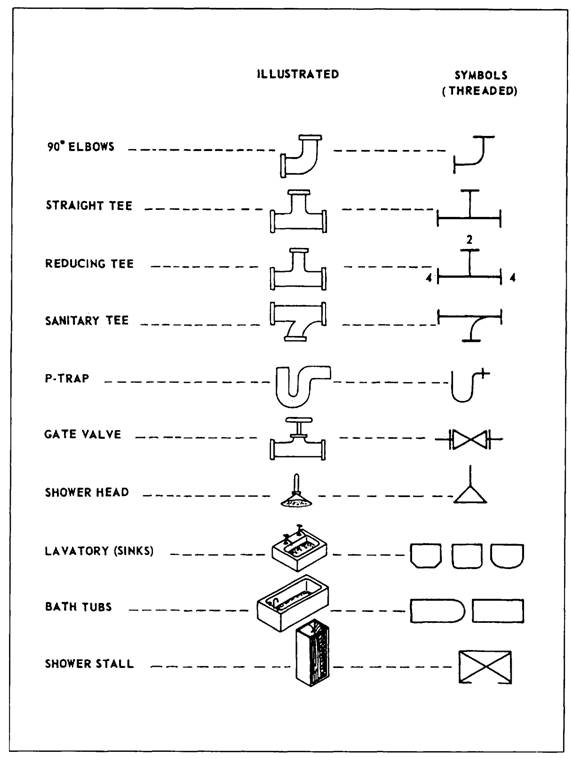
PLUMBING PRINTS Plumbing prints use many of the standard piping symbols shown in figure 5-9. MIL-STD-17B Parts I and 11 lists other symbols that are used only in plumbing prints, some of which are shown in figure 5-19.
Figure 5-17.-Aircraft power brake control valve system.
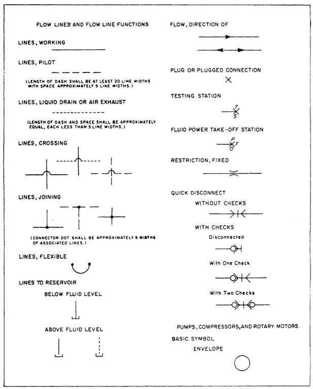
Figure 5-18.-Fluid power symbols.
Figure 5-19.-Common plumbing symbols.
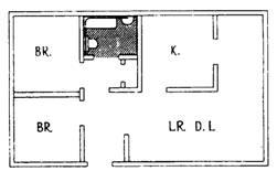
Figure 5-20 is a pictorial drawing of a bathroom. In the drawing, all that is normally placed in or under the floor has been exposed to show a complete picture of the plumbing, connections, and fixtures. Figure 5-21, views A and B, are isometric diagrams of the piping in the bathroom shown in figure 5-20. Figure 5-22 is a floor plan of a small house showing the same bathroom, including the locations of fixtures and piping. To interpret the isometric plumbing diagram shown in figure 5-21, view A, start at the lavatory (sink). You can see a symbol for a P-trap that leads to a tee connection. The portion of the tee leading upward goes to the vent, and the portion leading downward goes to the drain. You can follow the drain pipe along the wall until it reaches the corner where a 90-degree elbow is connected to bring the drain around the corner. Another section of piping is connected between the elbow and the next tee. One branch of the tee leads to the P-trap of the bathtub, and the other to the tee necessary for the vent (pipe leading upward between the tub and water closet). It then continues on to the Y-bend with a heel (a special
Figure 5-21.-Isometric diagram of a bathroom showing waste, vents, and water service.
Figure 5-20.-Pictorial view of a typical bathroom.
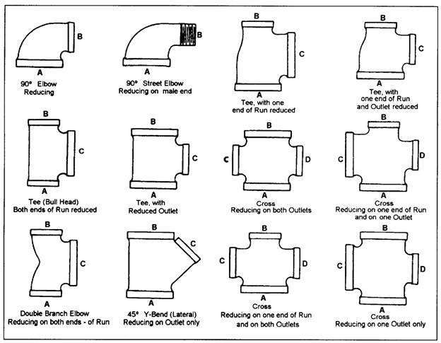
Figure 5-22.-Floor plan of a typical bathroom. fitting) that leads to a 4-inch main house drain. The vent pipe runs parallel to the floor drain, slightly above the lavatory. Figure 5-21, view B, is an isometric drawing of the water pipes, one for cold water and the other for hot water. These pipes are connected to service pipes in the wall near the soil stack, and they run parallel to the drain and vent pipes. Look back at figure 5-20 and you can see that the water service pipes are located above the drain pipe. Figure 5-23 shows you how to read the designations for plumbing fittings. Each opening in a fitting is identified with a letter. For example, the fitting at the right end of the middle row shows a cross reduced on one end of the run and on one outlet. On crosses and elbows, you always read the largest opening first and then follow the alphabetical order. So, if the fitting has openings sized 2 x 1/2 by 1 1/2 by 2 1/2 by 1 1/2 inches, you should read them in this order: A = 2 1/2, B = 1 1/2, C = 2 1/2, and D = 1 1/2 inches. On tees, 45-degree Y-bends or laterals, and double-branch elbows, you always read the size of the largest opening of the run first, the opposite opening of the run second, and the outlet last. For example, look at the tee in the upper right corner of figure 5-23 and assume it is sized 3 by 2 by 2 inches. You would read the openings as A = 3, B = 2, and C = 2 inches.
Figure 5-23.-How to read fittings. |
|
Privacy Statement - Press Release - Copyright Information. - Contact Us - Support Integrated Publishing |