 |
||
|
|
||
| |||||||||||||||
|
|
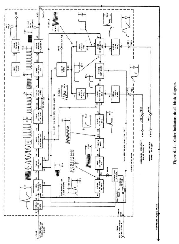
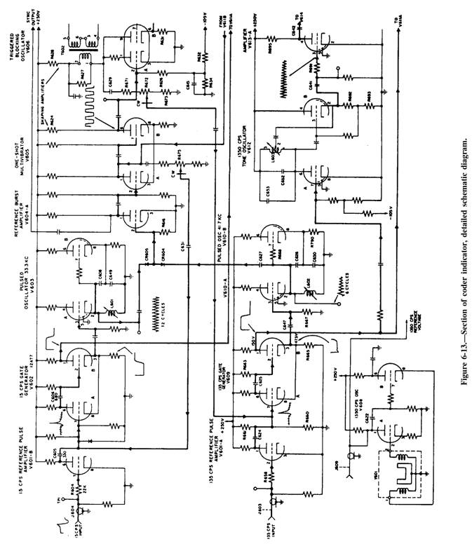
Schematic Diagrams Electronic schematic diagrams use graphic symbols from ANSI Y32.2 for all parts, such as tubes, transistors, capacitors, and inductors. Appendix III in this textbook shows common electronic symbols from this standard. Simplified schematic diagrams are used to show how a particular circuit operates electronically. However, detailed schematic diagrams are necessary for troubleshooting. Figure 6-13 shows a section of the detailed schematic diagram of the coder indicator show in figure 6-11. Some of the components in figure 6-13 are not numbered. In an actual detailed schematic, however, all components, such as resistors and capacitors, are identified by a letter and a number and their values are given. All tubes and transistors are identified by a letter and a number and also by type. Input signals are shown entering on the left (fig. 6-13) and signal flow is from left to right, which is the general rule for schematic diagrams. In the block diagram in figure 6-11, the north reference burst signal is shown applied to the pin 7 grid of V601B. The pin 6 plate output of V601B is fed to the pin 7 grid of V602, and the pin 3 cathode output of V602
is applied to the pin 3 grid of V603, and so on. In addition, the schematic diagram in figure 6-13 shows that the north reference burst signal is fed through 22K (22,000 ohms) resistor R604 grid 7 and that the plate output of V601B is coupled through capacitor C605 (a 330 picofared capacitor) to the grid of section A of V602, twin-triode type 12AT7 tube. Therefore, the detailed schematic diagram shows detailed information about circuits and parts and must be used in conjunction with the detailed block diagram to effectively troubleshoot a system. Wiring Diagrams Electronic equipment wiring diagrams show the relative positions of all equipment parts and all electrical connections. All terminals, wires, tube sockets, resistors, capacitors, and so on are shown as they appear in the actual equipment. Figure 6-14 shows a sample wiring diagram. Designations IAI, IAIAI, and IAIA2 are reference designations and will be discussed later. Figure 6-15 shows the basic wiring color code for electronic equipment. |
|
Privacy Statement - Press Release - Copyright Information. - Contact Us - Support Integrated Publishing |
|
|
Integrated Publishing, Inc. - A (SDVOSB) Service Disabled Veteran Owned Small Business
|