 |
||
|
|
||
| |||||||||||||||
|
|
SAFETY NOTE This is a dangerous operation and caution should be taken. Since abutting surfaces of end-mitered members do not hold well when they are merely glued, they should be reinforced. One type of reinforcement is the corrugated fastener. This is a corrugated strip of metal with one edge sharpened for driving into the joint. The fastener is placed at a right angle to the line between the members, half on one member and half on the other, and driven down flush with the member. The corrugated fastener mars the appearance of the surface into which it is driven; therefore, it is used only on the backs of picture frames and the like. A more satisfactory type of fastener for a joint between end-mitered members is the slip feather. This is a thin piece of wood or veneer that is glued
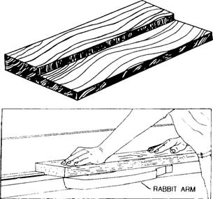
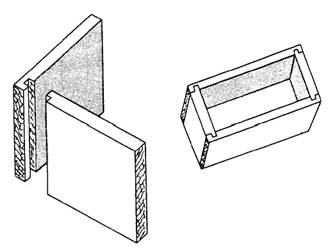
Figure 3-52.-Beveling on a jointer for a mitered edge joint. into a kerf cut in the thickest dimension of the joint. First, saw about halfway through the wood from the outer to the inner corner, then apply glue to both sides of the slip feather, pushing the slip feather into the kerf. Clamp it tightly and allow the glue to dry. After it has dried, remove the clamp and chisel off the protruding portion of the slip feather. A joint between edge-mitered members can also be reinforced with a spline. This is a thick piece of wood that extends across the joint into grooves cut in the abutting surfaces. A spline for a plain miter joint is shown in figure 3-44. The groove for a spline can be cut either by hand or by a circular saw. Grooved Joints A three-sided recess running with the grain is called a groove, and a recess running across the grain is called a dado. A groove or dado that does not extend all the way across the wood is called a stopped groove or a stopped dado. A stopped dado is also known as a gain (figure 3-46). A two-sided recess running along an edge is called a rabbet T (figure 3-45). Dadoes, gains, and rabbets are not, strictly speaking, grooves; but joints that include them are generally called grooved joints. A groove or dado can be cut with a circular saw as follows: Lay out the groove or dado on the end wood (for a groove) or edge wood (for a dado) that will first come in contact with the saw. Set the saw to the desired depth of the groove above the table, and set the fence at a distance from the saw that will cause the first cut to run on the waste side of the line that indicates the left side of the groove. Start the saw and bring the wood into light contact with it; then stop the saw and examine the layout to ensure the cut will be on the waste side of the line. Readjust the fence, if necessary. When the position of the fence is right, make the cut. Then, reverse the wood and proceed to set and test as before for the cut on the opposite side of the groove. Make as many recuts as necessary to remove the waste stock between the side kerfs. The procedure for grooving or dadoing with the dado head is about the same, except that, in many cases, the dado head can be built up to take out all the waste in a single cut. The two outside cutters alone will cut a groove 1/4 inch wide. Inside cutters vary in thickness from 1/16 to 1/4 inch. A stopped groove or stopped dado can be cut on the circular saw, using either a saw blade or a dado head, as follows: If the groove or dado is stopped at only one end, clamp a stop block to the rear of the table in a position that will stop the wood from being fed any farther when the saw has reached the place where the groove or dado is supposed to stop. If the groove or dado is stopped at both ends, clamp a stop block to the rear of the table and a starting block to the front. The starting block should be placed so the saw will contact the place where the groove is supposed to start when the infeed end of the piece is against the block. Start the cut by holding the wood above the saw, with the infeed end against the starting block and the edge against the fence. Then, lower the wood gradually onto the saw, and feed it through to the stop block. A rabbet can be cut on the circular saw as follows: The cut into the face of the wood is called the shoulder cut, and the cut into the edge or end, the cheek cut. To make the shoulder cut (which should be made first), set the saw to extend above the table a distance equal to the desired depth of the cheek. Be sure to measure this distance from a sawtooth set to the left, or away from the ripping fence. If you measure it from a tooth set to the right or toward the fence, the cheek will be too deep by an amount equal to the width of the saw kerf. By using the dado head, you can cut most ordinary rabbets in a single cut. First, build up a dado head equal in thickness to the desired width of the cheek. Next, set the head to protrude above the table a distance equal to the desired depth of the should. Clamp a 1-inch board to the fence to serve as a guide for the piece, and set the fence so the edge of the board barely contacts the right side of the dado head. Set the piece against the miter gauge (set at 90), hold the edge or end to be rabbeted against the 1-inch board, and make the cut. On some jointers, a rabbeting ledge attached to the outer edge of the infeed table can be depressed for rabbeting, as shown in figure 3-53. The ledge is located on the outer end of the butterhead. To rabbet on a jointer of this type, you depress the infeed table and the rabbeting ledge the depth of the rabbet below the outfeed table, and set the fence the width of the rabbet away from the outer end of the butterhead. When the piece is fed through, the unrabbeted part feeds onto the rabbeting ledge. The rabbeted portion feeds onto the outfeed table. Various combinations of the grooved joints are used in woodworking. The tongue-and-groove joint is a combination of the groove and the rabbet, with the tongued member rabbeted on both faces. In some types of paneling, the tongue is made by rabbeting only one face. A tongue of this kind is called a barefaced tongue. A joint often used in making boxes, drawers, and cabinets is the dado and rabbet joint, shown in figure 3-54. As you can see, one of the members is rabbeted on one face to form a barefaced tongue. Mortise-and-Tenon Joints The mortise-and-tenon joint is most frequently used in furniture and cabinet work. In the blind mortise-and-tenon joint, the tenon does not penetrate
Figure 3-53: Rabbeting on a jointer with a rabbeting ledge.
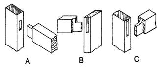
Figure 3-54.-Dado and rabbet joint. all the way through the mortised member (figure 3-47). A joint in which the tenon does penetrate all the way through is a through mortise-and-tenon joint (figure 3-55). Besides the ordinary stub joint (view A), there are haunched joints (view B) and table-haunched joints (view C). Haunching and table-haunching increase the strength and rigidity of the joint. The layout procedure for an ordinary stub mortise-and-tenon joint is shown in figure 3-56. The shoulder and cheek cuts of the tenon are shown in figures 3-57 and 3-58. To maintain the stock upright while making the cheek cuts, use a push board similar to the one shown in figure 3-58. Tenons can also be cut with a dado head by the same method previously described for cutting end half-lap joints.
Figure 3-55.-Stub (view A), haunched (view B), and table-haunched (view C) mortise-and-tenon joints.
Figure 3-56.-Layout of stub mortise-and-tenon joint.
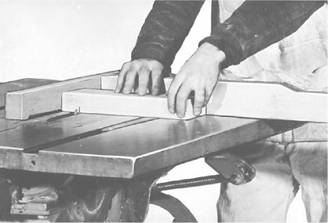
Figure 3-57.-Making tenon shoulder cut on a table saw.
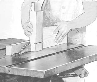
Figure 3-58.-Making tenon cheek cut on a table saw using a push board.
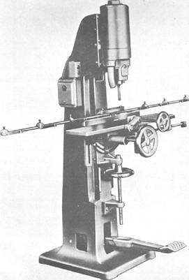
Figure 3-59.-Hollow-chisel mortising machine. Mortises are cut mechanically on a hollow-chisel mortising machine like the one shown in figure 3-59. The cutting mechanism on this machine consists of a boring bit encased in a square, hollow, steel chisel. As the mechanism is pressed into the wood, the bit takes out most of the waste while the chisel pares the sides of the mortise square. Chisels come in various sizes, with corresponding sizes of bits to match. If a mortising machine is not available, the same results can be attained by using a simple drill press to take out most of the waste and a hand chisel, for paring the sides square. In some mortise-and-tenon joints, such as those between rails and legs in tables, the tenon member is much thinner than the mortise member. Sometimes a member of this kind is too thin to shape in the customary reamer, with shoulder cuts on both faces. When this is the case, a barefaced mortise-and-tenon joint can be used. In a barefaced joint, the tenon member is shoulder cut on one side only. The cheek on the opposite side is simply a continuation of the face of the member. Mortise-and-tenon joints are fastened with glue and with additional fasteners, as required.
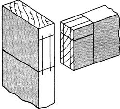
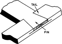
Figure 3-60.-Dovetail half-lap Joint. |
|
Privacy Statement - Press Release - Copyright Information. - Contact Us - Support Integrated Publishing |
|
|
Integrated Publishing, Inc. - A (SDVOSB) Service Disabled Veteran Owned Small Business
|