 |
||
|
|
||
| |||||||||||||||
|
|
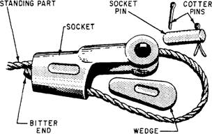
WIRE ROPE ATTACHMENTS Many attachments can be fitted to the ends of wire rope so that the rope can be connected to other wire ropes, pad eyes, or equipment. The attachment used most often to attach dead ends of wire ropes to pad eyes or like fittings on earthmoving rigs is the wedge socket shown in figure 4-14. The socket is applied to the bitter end of the wire rope, as shown in the figure. Remove the pin and knock out the wedge first. Then, pass the wire rope up through the socket and
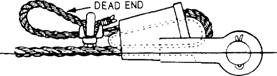
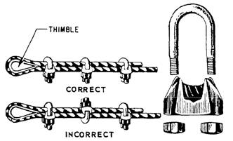
Figure 4-14.-Parts of a wedge socket. lead enough of it back through the socket to allow a minimum of 6 to 9 inches of the bitter end to extend below the socket. Next, replace the wedge, and haul on the bitter end of the wire rope until the bight closes around the wedge, as shown in figure 4-15. A strain on the standing part will tighten the wedge. You need at least 6 to 9 inches on the dead end (the end of the line that doesn't carry the load). Finally, place one wire rope clip on the dead end to keep it from accidentally slipping back through the wedge socket. The clip should be approximately 3 inches from the socket. Use one size smaller clip than normal so that the threads on the U-bolt are only long enough to clamp tightly on one strand of wire rope. The other alternative is to use the normal size clip and hop the dead end back as shown in figure 4-15. Never attach the clip to the live end of the wire rope. The advantage of the wedge socket is that it is easy to remove; just take off the wire clip and drive out the wedge. The disadvantage of the wedge socket is that it reduces the strength of wire rope by about 30 percent. Of course, reduced strength means less safe working load. To make an eye in the end of a wire rope, use new wire rope clips, like those shown in figure 4-16. The U-shaped part of the clip with the threaded ends is called the U-bolt; the other part is called the saddle. The saddle is stamped with the diameter of the wire rope that the clip will fit. Always place a clip with the U-bolt on the bitter end, not on the standing part of the wire rope. If clips are attached incorrectly, the standing part (live end) of the wire rope will be distorted or have mashed spots. An easy way to remember is never saddle a dead horse. You also need to determine the correct number of clips to use and the correct spacing. Here are two simple formulas. 3 x wire rope diameter + 1 = number of clips 6 x wire rope diameter = spacing between clips
Figure 4-15.-Wedge socket attached properly.
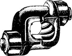
Figure 4-16.-Wire rope clips. Another type of wire rope clip is the twin-base clip (sometimes referred to as the "universal" or "two-clamp") shown in figure 4-17. Since both parts of this clip are shaped to fit the wire rope, correct installation is almost certain. This considerably reduces potential damage to the rope. The twin-base clip also allows for a clean 360 swing with the wrench when the nuts are being tightened. When an eye is made in a wire rope, a metal fitting (called a thimble) is usually placed in the eye, as shown in figure 4-16, to protect the eye against were. Clipped eyes with thimbles hold approximately 80 percent of the wire rope strength. After the eye made with clips has been strained, the nuts on the clips must be retightened. Occasional checks should be made for tightness or damage to the rope caused by the clips.
Figure 4-17.-Twin-base wire clip.
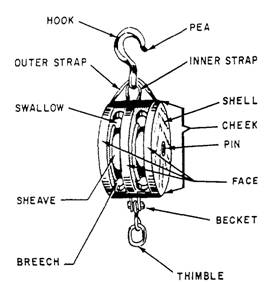
Figure 4-18.-Nomenclature of a fiber line block. BLOCK AND TACKLE LEARNING OBJECTIVE: Upon completing this section, you should be able to identify the components and operating characteristics of block and tackle units.
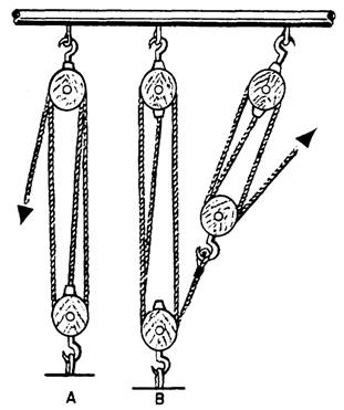
Figure 4-19.-Types of tackle: simple (view A) and compound (view B). A block (figure 4-18) consists of one or more sheaves fitted in a wood or metal frame supported by a shackle inserted in the strap of the block. A tackle (figure 4-19) is an assembly of blocks and lines used to gain a mechanical advantage in lifting and pulling. In a tackle assembly, the line is reeved over the sheave(s) of blocks. The two types of tackle systems are simple and compound. A simple tackle system is an assembly of blocks in which a single line is used (view A of figure 4-19). A compound tackle system is an assembly of blocks in which more than one line is used (view B of figure 4-19). |
|
Privacy Statement - Press Release - Copyright Information. - Contact Us - Support Integrated Publishing |