 |
||
|
|
||
| |||||||||||||||
|
|
BEARING WALL FOOTINGS.- Figure 7-4 shows a typical footing formwork for a bearing wall, and figure 7-5 shows bracing methods for a bearing
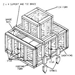
Figure 7-3.-Footing and pier form.
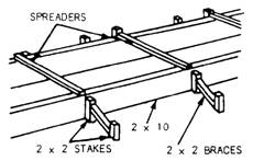
Figure 7-4.-Typical footing form. wall footing. A bearing wall, also called a loadbearing wall, is an exterior wall that serves as an enclosure and also transmits structural loads to the foundation. The form sides are 2-inch lumber whose width equals the footing depth. Stakes hold the sides in place while spreaders maintain the connect distance between them. The short braces at each stake hold the form in line. A keyway is made in the wet concrete by placing a 2-by-2-inch board along the center of the wall footing form. After the concrete is thy, the board is removed. This leaves an indentation, or key, in the concrete. When you pour the foundation wall, the key provides a tie between the footing and wall. Although not discussed in this training manual, there are several commercial keyway systems available for construction projects. Columns Square column forms are made of wood. Round column forms are made of steel, or cardboard
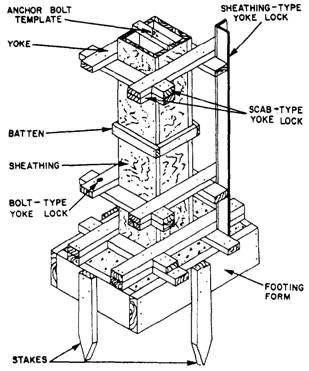
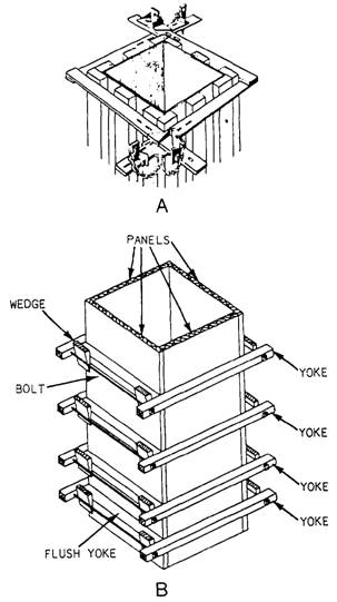
Figure 7-5.-Methods of bracing bearing wall footing forms and placing a keyway. impregnated with waterproofing compound. Figure 7-6 shows an assembled column and footing form. After constructing the footing forms, build the column form sides, and then nail the yokes to them. Figure 7-7 shows a column form with two styles of yokes. View A shows a commercial type, and view B shows yokes made of all-thread bolts and 2-by material. Since the rate of placing concrete in a column form is very high and the bursting pressure exerted on the form by the concrete increases directly with the rate of placing, a column form must be securely braced, as shown by the yokes in the figure. Because the bursting pressure is greater at the bottom of the form than it is at the top, yokes are placed closer together at the bottom. The column form should have a clean-out hole cut in the bottom from which to remove construction debris. Be sure to nail the pieces that you cut to make the clean-out hole to the form. This way, you can replace them exactly before placing concrete in the column. The intention of the clean-out is to ensure that the surface which bonds with the new concrete is clear of all debris.
Figure 7-6.-Form for a concrete column.
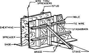
Figure 7-7.-Column form with scissor clamp (View A), and yolk and wedge (View B). Walls Wall forms (figure 7-8) may be built in place or prefabricated, depending on shape and desirability of
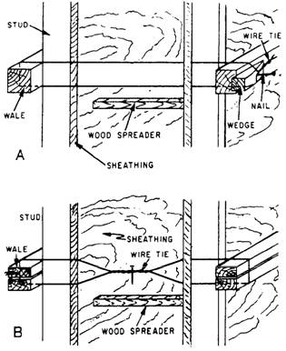
Figure 7-8.-Form for a concrete wall. form reuse. Some of the elements that make up wooden forms are sheathing, studs, wales, braces, shoe plates, spreaders, and tie wires. CONSTRUCTION.- Sheathing forms the surfaces of the concrete. It should be as smooth as possible, especially if the finished surfaces are to be exposed. Since the concrete is in a plastic state when placed in the form, the sheathing should be watertight. Tongue-and-groove sheathing gives a smooth, watertight surface. Plywood or hardboard can also be used and is the most widely accepted construction method. The weight of the plastic concrete causes sheathing to bulge if it is not reinforced. As a result, studs are run vertically to add rigidity to the wall form. Studs are generally made from 2-by-4 or 3-by-6 material. Studs also require reinforcing when they extend over 4 or 5 feet. This reinforcing is supplied by double wales. Double wales also serve to tie prefabricated panels together and keep them in a straight line. They run horizontally and are lapped at the corners of the forms to add rigidty. Wales are usually made of the same material as the studs. The shoe plate is nailed into the foundation or footing. It is carefully placed to maintain the correct wall dimension and alignment. The studs are tied into the shoe and spaced according to the correct design. Small pieces of wood are cut the same length as the thickness of the wall and are placed between the forms to maintain proper distance between forms. These pieces are known as spreaders. The spreaders are not nailed but are held in place by friction and must be removed before the concrete covers them. A wire should be securely attached to each spreader so that the spreaders can be pulled out after the concrete has exerted enough pressure on the walls to allow them to be easily removed. he wire is designed to hold the forms securely against the lateral pressure of unhardened concrete. A double strand of tie wire is always used. BRACING.- Many types of braces can be used to add stability and bracing to the forms. The most common type is a diagonal member and horizontal member nailed to a stake and to a stud or wale, as shown in figure 7-8. The diagonal member should make a 30 angle with the horizontal member. Additional bracing may be added to the form by placing vertical members (strongbacks) behind the wiles or by placing vertical members in the corner formed by intersecting wales. Braces are not part of the form design and are not considered as providing any additional strength. REINFORCEMENT.- Wall forms are usually reinforced against displacement by the use of ties. Two types of simple wire ties, used with wood spreaders, are shown in figure 7-9. The wire is passed around the studs, the wiles, and through small holes bored in the sheathing. Each spreader is placed as close as possible to the studs, and the tie is set taut by the wedge, as shown in view A of figure 7-9, or by twisting with a small toggle, as shown in view B. As the concrete reaches the level of each spreader, the spreader is knocked out and removed. Figure 7-10 shows you an easy way to remove the spreaders by drilling holes and placing a wire through them. The parts of the wire that are inside the forms remain in the concrete; the outside surplus is cut off after the forms are removed.
Figure 7-9.-Wire ties for wall forms.
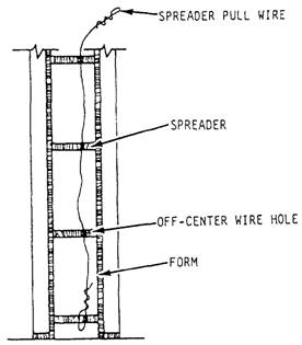
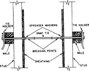
Figure 7-10.-Removing wood spreaders. Wire ties and wooden spreaders have been largely replaced by various manufactured devices in which the function of the tie and the function of the spreader are combined. Figure 7-11 shows one of these. It is called a snap tie. These ties are made in various sizes to tit various wall thicknesses. The tie holders can be removed from the tie rod. The rod goes through small holes bored in the sheathing, and also through the
Figure 7-11.-Snap tie. wales, which are usually doubled for that purpose. Tapping the tie holders down on the ends of the rod brings the sheathing to bear solidly against the spreader washers. You can prevent the tie holder from coming loose by driving a duplex nail in the provided hole. After the concrete has hardened, the tie holders can be detached to strip the forms. After the forms are stripped, a special wrench is used to break off the outer sections of rods. The rods break off at the breaking points, located about 1-inch inside the surface of the concrete. Small surface holes remain, which can be plugged with grout if necessary. Another type of wall-form tie is the tie rod (figure 7-12). This rod consists of an inner section that is threaded on both ends and two threaded outer sections. The inner section with the cone nuts set to the thickness of the wall is placed between the forms, and the outer sections are passed through the wales and sheathing and threaded into the cone nuts. The clamps are then threaded on the outer sections to bring the forms to bear against the cone nuts. After the concrete hardens, the clamps are loosened, and the outer sections of rod are removed by threading them out of the cone nuts. After the forms are stripped, the cone nuts are removed from the concrete by threading them off the inner sections of the rod with a special wrench. The cone-shaped surface holes that remain can be plugged with grout. The inner sections of the rod remain in the concrete. The outer sections and the cone nuts may be reused indefinitely. Wall forms are usually constructed as separate panels. Make the panels by first nailing sheathing to the studs. Next, connect the panels, as shown in
Figure 7-12.-Tie rod.
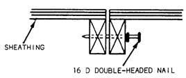
Figure 7-13.-Joining wall form panels together in line. figure 7-13. Figure 7-14 shows the form details at the wall corner. When placing concrete panel wails and columns at the same time, construct the wall form, as shown in figure 7-15. Make the wall form shorter than the distance between the column forms to allow for a wood strip that acts as a wedge. When stripping the forms, remove the wedge first to aid in form removal. |
|
Privacy Statement - Press Release - Copyright Information. - Contact Us - Support Integrated Publishing |