Custom Search
|
|
  |
|
|
INSTALLING GUYS
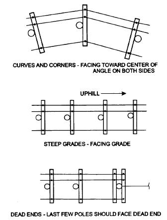
Figure 4-57.- Pole facing. Guys are assembled using seven-strand galvanized steel guy wire, a strain insulator (of a different design from and not to be confused with the strain insulator used for dead ending a conductor), and three bolt clamps or preformed guy grips. The dimensioning of the guy is determined by the height of the pole, by the amount of strain to be counteracted, and by the climate when the guy is installed. Figure 4-59 shows a typical guy and the method of attaching the come-along for tensioning the guy. INSTALLING CROSSARMS As previously discussed in this chapter, crossarms come in various sizes and types, depending on the type of system, size and number of conductors, and voltage of the system.
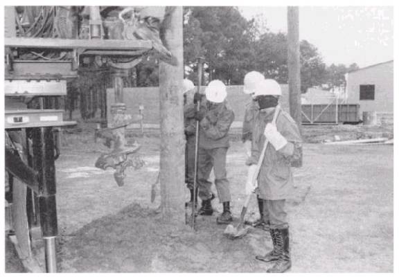
Figure 4-58.- Tamping and backfilling erected pole.
Figure 4-59.- Pulling guys to anchor utility pole.
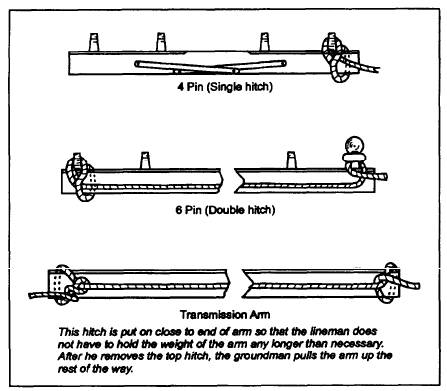
Figure 4-60.- Crossarm, showing proper way to attach a handline. On most pole-line construction, the installation of hardware and crossarms is accomplished on the ground before setting the pole. This is the easiest and most efficient method; however, sometimes it is necessary to upgrade or build on to an existing system, and then the arm must be installed on a pole that is already standing. When the crossarm is mounted on the pole before the pole is set, the through bolt is tightened, but the crossarm braces are left hanging loose. Once the pole is set, the crossarm is leveled and the braces are secured to the pole. Finally, the through bolt is drawn completely tight. When the crossarm is mounted after the pole is set, it is pulled up to a lineman in a working position by a helper on the ground, using a handline attached, as shown in figure 4-60. With the handline attached in this fashion, the lineman can, after he inserts the through bolt, cast off the upper half-hitch, and the helper on the ground can then heave the crossarm level. Braces are usually fastened to a crossarm with 3/ 8-inch by 4-inch carriage bolts. Each brace comes down diagonally and is attached to the pole at the lower end with a 1/ 2-inch lag screw.
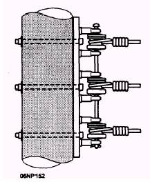
Figure 4-61.- Dead-end secondary rack. On a straight line without excessive strains, crossarms are used singly-mounted face-to-face or back-to-back, as previously mentioned. At line terminals, corners, angles, or other points of excessive strain, crossarms are doubled. When a power line crosses a railroad or a telephone line, crossarms should also be doubled. When double arms are used, they are fastened together at the ends with double-arm bolts. One of these is threaded all the way and has two square washers and two nuts on each bolt between the arms. The lineman can adjust the spacing between a pair of crossarms by setting these nuts the desired distance apart on the threaded bolts.
|
 
|
|
|