Custom Search
|
|
  |
|
|
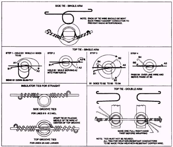
TARGETS.- The target-sighting method is a simple and accurate means for measuring sag. The TYING IN CONDUCTORS Tie wire fastens the conductor and insulator together. Conductors can be tied in various ways, but the ties shown in figure 4-68 are the ones most desired sag is first determined from table 4-2. commonly used.
Figure 4-68.- Tying in conductors. A special reminder- When using an aluminum conductor, you are required to cover it with armor rod at each insulator to provide physical protection against rubbing or pitting caused by the elements. Another important requirement is the use of ACSR-rated dead-end shoes, splice connectors, and all other devices that come in direct contact with an aluminum conductor. This is to prevent electrolysis that occurs from the physical contact of dissimilar metals. In tying in conductors, observe the following procedures: Always use new, fully annealed wire for ties. Hard-drawn wire is brittle and cannot be pulled up against the conductor and insulator. Use the proper size wire. For No. 8 bare, use No. 8 bare. For No. 6 or No. 4 bare, use No. 6 bare. Use No. 4 bare for a No. 2 conductor. Use No. 2 bare wire for No. l/ O through 4/ 0 bare conductor. Use a piece of tie wire that is long enough to make the complete tie, with enough left over to allow grasping. After the tie is completed, cut off the excess and form a loop, or eye, at the end of any projecting end of the wire. Make positive contact between the wire and conductor to avoid chafing and to limit possibilities of causing interference with radio communications. Hold the tie wire tight against the insulator as you make your wraps around the insulator and the conductor wire. INSTALLING GROUNDS Grounding in the power distribution system is important. The grounding system protects you and the
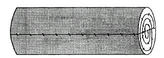
Figure 4-69.- Pole with butt ground plate.
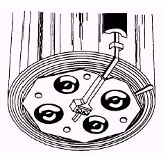
Figure 4-70.- Pole butt ground, coiled wire type. distribution system when faults occur and aids in the suppression of noise. Grounds are required every quarter mile on a power distribution line and at every pole when equipment, such as transformers, regulators, capacitors, switches, circuit breakers, and lightning arresters, is installed. The maximum resistance of any distribution ground is 25 ohms, but a lower resistance is desired. In new construction a butt ground is placed on the pole before the pole is installed. The butt ground can be a manufactured plate, as shown in figure 4-69, or a coil of bare copper wire, as shown in figure 4-70. On existing distribution lines, a ground rod that is 5/ 8 inch in diameter and 8 feet long is driven at the base of the pole and tied to the pole with a bare copper grounding conductor and a ground clamp, as shown in figure 4-71.
Figure 4-71.- Pole ground, ground rod type. The ground wire on the pole is covered by molding from the level of earth to a height of 8 feet. On the top of the pole, the grounding conductor is connected to the cases of all installed equipment, lightning arresters, and the primary and secondary neutrals of the distribution system, as shown in figure 4-72. easier your work will be. Yet, no matter how good you become at climbing, the potential for a serious accident always exists when you work around high voltage. In this section you will look at the proper methods of maintaining equipment, climbing poles, and performing emergency rescue from the pole and aerial bucket truck.
|
|
|
|