Custom Search
|
|
  |
|
|
CHAPTER 6 COMMUNICATIONS AND LIGHTING Many advances in lighting and communications have occurred in the past few years. With the cost of energy rising daily and the demand for accurate and reliable communications, any system that provides a higher level of efficiency must be considered. In this chapter we will discuss public address systems, interoffice communications, and the fundamentals of fiber-optic communication cables and components. This chapter also will cover area streetlighting, floodlighting, and security lighting. PUBLIC ADDRESS SYSTEM The type of public address system that you will install, maintain, and troubleshoot is intended for installation in administrative and living quarter areas. This system will be used for general announcements, for indoor talk-back paging, and to entertain or address personnel. A common system authorized by the General Services Administration consists of one 100-watt solid-state amplifier, four trumpet speakers with drivers, two paging speakers, one dynamic microphone with floor stand, and all accessory terminal fittings and hardware required to operate this system. The set will conform to the design and functional test requirements of Underwriters Laboratory (UL) 813 Standard and the wiring and design requirements of the National Fiie Protection Association (NFPA) 70. INSTALLATION Before you install a public address system, refer to the National Electrical Code(c) (NEC(c)) and the manufacturers' recommendations. Several factors must be met for the permanent or temporary installation of a public address (PA.) system. We will discuss these factors for the installation of a public address system, consisting of an amplifier (console), speakers, and cable that are approved for this system. Amplifier The solid-state amplifier comes with an ac power cord that is terminated in a three-prong plug. The power cord must be plugged into a three-wire, 120-volt, 60- hertz grounded outlet. The cord will ground the amplifier and the auxiliary power receptacle. The auxiliary power receptacle is a three-wire grounded outlet that supplies power to accessory sound equipment. The receptacle will supply power only as long as the amplifier is connected to a 120-volt power source and turned on. The amplifier will be internally wired with a circuit breaker for protection. If the breaker trips, turn off the amplifier and reset the circuit breaker. Turn on the amplifier, and, if the breaker trips again, do not attempt to reset it. A problem investigate and correct. Speakers exists that you will need to The speakers willbe weatherproof and have adjustable mounting brackets. The input impedance of the speakers will match the amplifier output with a low-frequency cutoff, as shown in figure 6-1.
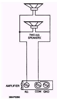
Figure 6-1.- Total speaker impedance matches the output impedance of the amplifier. The output speaker voltage will be either 25 or 70.7 volts. The speaker will have a microphone precedence over other input singles and four output terminals with circuit protection. Speaker installation is an important element whenever you install a P. A. system. No matter how good the amplifier is, if the speaker installation is not done properly, the sound produced will be inadequate. There are a number of factors you must consider when you install speakers. The placement and connection of speakers is the most important step. For indoor systems, two types of placement can be used. The speakers may be placed flat against a wall and the speaker turned so that it will radiate sound at an angle from the wall. The other type of placement is to mount the speakers in the corners of a room; for example, alcoves, balconies, booths, and dividing walls. A variation of these two methods mentioned may be considered for installation. For outdoor systems, the main considerations are the area to be covered and the direction of sound. Highly directive trumpet speakers are normally used for an outdoor area. When connecting speakers together, you must consider impedance matching and phase relations. Mismatching the impedance of a speaker to an amplifier output in either an upward or a downward manner will produce different effects. Mismatching upward (connecting an 8-ohm speaker to the 4-ohm output) will affect the power delivered to the speaker. Power loss will be about proportional to the upward impedance mismatch; in this case, about 50 percent. As a general rule, no serious frequency response deficiency will be noted and cannot damage a well-designed amplifier. Mismatching downward (connecting a 4-ohm speaker to an 8-ohm output) should always be avoided. It will reduce the amplifier power output and cause an overload on the output side with possible damage to the amplifier. Figure 6-2 shows an example of two speakers connected in series. Add the individual speaker impedances together to obtain the total matching impedance. The formula for this where Z = impedance is Zt = Z1 + Z2. For parallel connection (fig. 6-3) add the reciprocal of the individual speaker impedances together to obtain the reciprocal of the total matching impedance. The formula for parallel connections is as follows: For series/ parallel connections, combine the two formulas as the speaker connections indicate; for example, see figure 6-4, and apply the series formula for
Figure 6-2.- Two speakers connected in series. A and B, then for C and D. Take the results of this and apply the parallel formula 1/Zt=1/Z1+1/Z2 or (Z1*Z2)/(Z1+Z2) to obtain the final matching impedance.
Figure 6-3.- Matching two speakers connected in parallel.
Figure 6-4.- Matching four speakers connected in series parallel. When you use more than one speaker in a sound system installation, phase the speakers to reduce the cancellation effect, as shown in figure 6-5. Speakers out of phase will lose up to one half of their normal volume and operate with degraded tone quality. For speakers facing in the same general direction, they are in phase when their respective diaphragms move in the same direction. This is achieved by connecting the speakers + to + and -to -. For speakers facing each other, they are in phase when their respective diaphragms move in opposite Directions. This is achieved by connecting the speakers + to -and -to +. Efficient transfer of power from the amplifier to the speakers is the prime consideration in sound system connections. Basically, there are two methods of connection. One connection runs from the amplifier directly to the speaker voice coils and the other connection runs from the amplifier to the speaker voice coils through a transformer. You should use the first method with short runs (not over 200 feet) of wire and a simple speaker arrangement with low impedances. Use the second method whenever a 15-percent power loss in the transmission lines is noted or when wire runs are more than 200 feet, or there is a complex speaker arrangement. Constant voltage transformers are most commonly used for this purpose although impedance-matching transformers may be used. For an in-depth look, refer to NEETS, Module 8, Introduction to Amplifiers.
|
 
|
|
|