Custom Search
|
|
  |
|
|
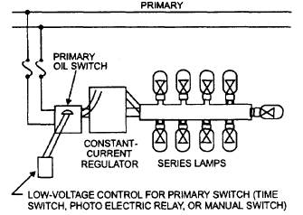
LIGHT CIRCUITS As we stated earlier, a number of light systems are in use today, such as streetlights, floodlights, and security lights. These systems are either series or multiple (parallel), depending on how they are used and the equipment available. SERIES AND MULTIPLE CIRCUITS The series circuit is supplied by a regulating transformer that gives a constant current, usually of 6.6 amperes, to the lighting circuit. If a higher amperage is required, autotransformers are available for stepping up the current to 15 or 20 amperes. This higher amperage permits the use of more rugged lamp filaments that give longer life for lamps of equal candlepower and higher lamp efficiency. The multiple (parallel) circuit consists of a number of streetlights supplied by a distribution transformer, delivering a constant low voltage to a circuit or secondary main that also supplies other loads; however, running secondary conductors any great distance to supply a parallel connected lamp or a group of lamps is impractical because of the excessive voltage drop. The cost of the multiple luminaire is low compared to the series type because the low voltage allows for the elimination of other luminaire accessories. This saving is largely offset, however, by the increased requirement for control devices and the copper wire cost. Lamp life and efficiency are comparatively low, and the illumination is not as uniform as in a series circuit. In choosing a system, here are a few suggestions that may aid in your selection. If the total wattage of the circuit exceeds 2 kilowatts or more than 15 lights, consider a series lighting system. When extending an existing system, use the existing circuit. If low-voltage capacity exists at the proposed location, use a multiple system, even though the load exceeds 2 kilowatts. When several small lights are to be spaced rather far apart and no low-voltage secondary exists along the route, use the series system regardless of the load size or the number of lights. When estimates show that one type of system will save money and time, use the more economical system. Series Circuits Let us consider a series streetlight system. The power for the circuit will be supplied from the base primary distribution lines, through fuse cutouts, to an oil switch, and from the oil switch to a constant-current regulator (fig. 6-16). The constant-current regulator will supply power to the series loops and, thus to the individual lamps. While the current (normally 6.6 amperes) remains constant, the voltage of the circuit is equal to the sum of the voltages of all the lamps plus the voltage drop in the wire. With enough lamps connected in series, the circuit can become a high-voltage circuit. The series circuit is easily controlled, but any break, such as a burned-out filament in a lamp, interrupts the
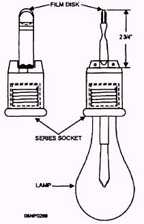
Figure 6-16.- Series street-lighting circuit. entire circuit. The use of film-disk cutouts (fig. 6-17) in the lamp socket prevents lamp failure from interrupting the circuit. The cutouts consist of two metal disks separated by a thin film of insulating material. The insulating film is held in place by the spring pressure of the contact disks. When the filament of the lamp burns out, the entire circuit voltage appears across the film disk. This is more than sufficient to puncture the film and close the circuit between the two metallic disks, thereby bypassing the burned-out filament. In later series circuits, an isolation transformer is used to eliminate the need for the film disk fixture. The primary winding of the isolation transformer is connected in series with the power source and the secondary winding provides power to the light bulb. Since the primary winding is isolated from the secondary winding, a burned out bulb will not interrupt the continuity of the lighting circuit. A series circuit is installed using only one wire, as shown in figure 6-18( a). Some of the lamps are connected in the outgoing wire, and the rest are connected in the return wire. This is called an "open-loop" series circuit. An open-loop circuit is less expensive initially, but troubleshooting is difficult, time consuming, and costly. To make it possible to locate a fault like an open circuit or a ground, it is desirable to bring the outgoing and return conductors close together in numerous places so that the circuit can be easily short-circuited. Such a circuit is called a "closed-loop" circuit, as shown in figure 6-18( b). Sometimes the circuit is arranged to combine the open-and closed-circuit features, as shown
Figure 6-17.- Series lamp, socket, and film-disk cutout.
Figure 6-18.- Diagrams of (a) open loop, (b) closed bop, and (c) combined open and closed loop series circuits. in figure 6-18( c). The use of the closed-loop or the combination circuit makes troubleshooting easier. Installing the series circuit on the same crossarm as the primary-distribution conductor is usually the most economical. When two primary crossarms are used, the streetlight wires should be carried on the lower arm in the end-pin position. When two separate single-conductor street circuits are on the same crossarm, they should not be placed in adjacent pin positions because of confusion in troubleshooting. Insulator sizes should be based on the open-circuit voltage of the largest regulator used and are usually the same size as those used for primary distribution. White insulators should be used on a series street circuit to distinguish them from the primary distribution insulators and to assist in identifying the circuits for operating and maintenance work. Small strain insulators should be used for cutting in individual lamps or loops of five lamps or fewer. Equivalent voltage insulators with automatic line splices may also be used. If the loop consists of more than five lamps, a primary disk insulator is used. The insulator is usually cut in after the conductors have been strung. The conductor size should be No. 6 medium hard-drawn copper or its mechanical equivalent. Although No. 8 hard-drawn copper is usually too weak for longer spans, the use of copperweld or similar conductors of
Figure 6-19.- Multiple street-lighting circuit. high-mechanical strength overcomes the difficulty. Conductor sag should be the same as for primary distribution. Constant-current regulators should be protected on overhead circuits by lightning arresters on both the primary and secondary sides. Multiple Circuits The multiple streetlight system uses a distribution transformer of the proper size as service equipment. (See fig. 6-19.) Notice that the transformer is fed directly through fuse cutouts from the base primary distribution system. The control for the circuit is connected into one line of the secondary side. The selection of output voltage of the transformer depends on the voltage required for the individual lamps that are installed. Depending on the types of lamps selected, this voltage may be from 120 volts to 480 volts. You must know the type of lamp that will be used in the circuit before you can properly select the transformer to feed the streetlight system. COMPONENTS AND CONTROLS There are many components required to construct an area lighting system. These include constant-current transformers, relays, controls, fixtures, wiring, and lamps. Controls can be manual, automatic, or a combination.
Figure 6-20.- Method of relieving slightly overloaded regulators with a distribution or booster transformer.
|
 
|
|
|