Custom Search
|
|
 
|
||
|
PRIMARY MAINS The primary mains are connected to the feeder at the distribution load center. They are always located below the feeder on a pole. The primary
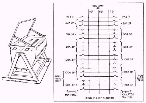
Figure 5-13.\Advanced base distribution center.
mains operate at the same voltage as the feeder. The distribution transformers are connected to the primary mains through fused or automatic cutouts. Figure 5-14 shows the primary main to which the transformer is tapped. The cutouts, one on each primary line, contain the fuses that protect the transformer against overload and short circuits. The primary mains are strung across the upper crossarm and usually lie in a horizontal DISTRIBUTION TRANSFORMERS Most electrical equipment in the Navy uses 120/208 volts. The primary voltage distributed on Navy shore installations, however, is usually 2,400/4,160 volts. A distribution transformer (step-down) is therefore required to reduce the high primary voltage to the utilization voltage of 120/208 volts. The various types of transformer installations are discussed later in this chapter. Regardless of the type of installation or arrangement, transformers must be protected by cutout fuses or circuit breakers, and lightning arresters should be installed between the highvoltage line and the fused cutouts. There are three general types of single-phase distribution transformers. The conventional type
Figure 5-14.\Pole-mounted primary mains. requires a lightning arrester and fused cutout on the primary phase conductor feeding it. The self-protected (SP) type has a built-in lightning protector; the completely self-protected (CSP) type has the lightning arrester and currentoverload devices connected to the transformer and requires no separate protective devices. |
 
|
|
|
||
|
|
Integrated Publishing, Inc. - A (SDVOSB) Service Disabled Veteran Owned Small Business
|