Custom Search
|
|
 
|
||
|
The scintillation counter is a solid state radiation detector. EO 2.7 DESCRIBE the operation of a scintillation counter to include: a. Radiation detection b. Three classes of phosphors c. Photomultiplier tube operation The scintillation counter is a solid state radiation detector which uses a scintillation crystal (phosphor) to detect radiation and produce light pulses. Figure 24 is important in the explanation of scintillation counter operation.
Figure 24 Electronic Energy Band of an Ionic Crystal As radiation interacts in the scintillation crystal, energy is transferred to bound electrons of the crystal's atoms. If the energy that is transferred is greater than the ionization energy, the electron enters the conduction band and is free from the binding forces of the parent atom. This leaves a vacancy in the valence band and is termed a hole. If the energy transferred is less than the binding energy, the electron remains attached, but exists in an excited energy state. Once again, a hole is created in the valence band. By adding impurities during the growth of the scintillation crystal, the manufacturer is able to produce activator centers with energy levels located within the forbidden energy gap. The activator center can trap a mobile electron, which raises the activator center from its ground state, G, to an excited state, E. When the center de-excites, a photon is emitted. The activator centers in a scintillation crystal are referred to as luminescence centers. The emitted photons are in the visible region of the electromagnetic spectrum. Scintillation counters are constructed by coupling a suitable scintillation phosphor to a lightsensitive photomultiplier tube. Figure 25 illustrates an example of a scintillation counter using a thallium-activated sodium iodide crystal.
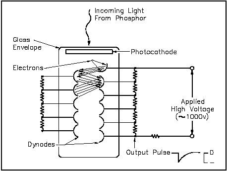
Figure 25 Scintillation Counter There are three classes of solid state scintillation phosphors: organic crystals, inorganic crystals, and plastic phosphors. Inorganic crystals include lithium iodide (LiI), sodium iodide (NaI), cesium iodide (CsI), and zinc sulfide (ZnS). Inorganic crystals are characterized by high density, high atomic number, and pulse decay times of approximately 1 microsecond. Thus, they exhibit high efficiency for detection of gamma rays and are capable of handling high count rates. Organic scintillation phosphors include naphthalene, stilbene, and anthracene. The decay time of this type of phosphor is approximately 10 nanoseconds. This type of crystal is frequently used in the detection of beta particles. Plastic phosphors are made by adding scintillation chemicals to a plastic matrix. The decay constant is the shortest of the three phosphor types, approaching 1 or 2 nanoseconds. The plastic has a high hydrogen content; therefore, it is useful for fast neutron detectors. A schematic cross-section of one type of photomultiplier tube is shown in Figure 26. The photomultiplier is a vacuum tube with a glass envelope containing a photocathode and a series of electrodes called dynodes. Light from a scintillation phosphor liberates electrons from the photocathode by the photoelectric effect. These electrons are not of sufficient number or energy to be detected reliably by conventional electronics. However, in the photomultiplier tube, they are attracted by a voltage drop of about 50 volts to the nearest dynode.
Figure 26 Photomultiplier Tube Schematic Diagram The photoelectrons strike the first dynode with sufficient energy to liberate several new electrons for each photoelectron. The second-generation electrons are, in turn, attracted to the second dynode where a larger third-generation group of electrons is emitted. This amplification continues through 10 to 12 stages. At the last dynode, sufficient electrons are available to form a current pulse suitable for further amplification by transistor circuits. The voltage drops between dynodes are established by a single external bias, approximately 1000 volts dc, and a network of external resistors to equalize the voltage drops. The advantages of a scintillation counter are its efficiency and the high precision and counting rates that are possible. These latter attributes are a consequence of the extremely short duration of the light flashes, from about 10-9 to 10-6 seconds. The intensity of the light flash and the amplitude of the output voltage pulse are proportional to the energy of the particle responsible for the flash. Consequently, scintillation counters can be used to determine the energy, as well as the number, of the exciting particles (or gamma photons). The photomultiplier tube output is very useful in radiation spectrometry (determination of incident radiation energy levels). Summary The operation of scintillation counters is summarized below. Scintillation Counter Summary Radiation interactions with a crystal center cause electrons to be raised to an excited state. When the center de-excites, the crystal emits a photon in the visible light range. Three classes of phosphors are used: inorganic crystals, organic crystals, and plastic phosphors. The photon, emitted from the phosphor, interacts with the photocathode of a photomultiplier tube, releasing electrons. Using a voltage potential, the electrons are attracted and strike the nearest dynode with enough energy to release additional electrons. The second-generation electrons are attracted and strike a second dynode, releasing more electrons. This amplification continues through 10 to 12 stages. At the final dynode, sufficient electrons are available to produce a pulse of sufficient magnitude for further amplification.
|
||
|
||