Custom Search
|
|
 
|
||
|
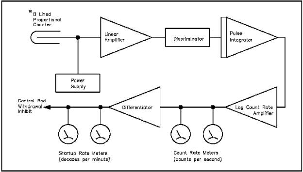
Three ranges are used to monitor the power level of a reactor throughout the full range of reactor operation. The source range makes use of a proportional counter. EO 3.3Given a block diagram of a typical source range instrument, STATE the purpose of major components. a. Linear amplifier b. Discriminator c. Pulse integrator d. Log count rate amplifier e. Differentiator Source range instrumentation normally consists of two redundant count rate channels, each composed of a high-sensitivity proportional counter and associated signal measuring equipment. These channels are typically used over a counting range of 0.1 to 106 counts per second, but vary based on reactor design. Their outputs are displayed on meters in terms of the logarithm of the count rate. Source range instrumentation also measures the rate of change of the count rate. The rate of change is displayed on meters in terms of the startup rate from -1 to +10 decades per minute. Protective functions are not normally associated with source range instrumentation because of inherent limitations in this range. However, interlocks may be incorporated. Many reactor plants have found it necessary to place source range proportional counters in lead shielding to reduce gamma flux at the detectors. This serves two functions: (a) it increases the low end sensitivity of the detector, and (b) it adds to detector life. Another means by which detector life is extended is to disable the high voltage power supply to the detector and short the signal lead when neutron flux has passed into the intermediate range. There are some reactor plants that have made provisions for moving the source range detectors from their operating positions to a position of reduced neutron flux level, once the flux level increases above the source range. Figure 35 shows a typical source range channel in functional form.
Figure 35 Source Range Channel B10 lined or BF3 gas-filled proportional counters are normally used as source range detectors. Proportional counter output is in the form of one pulse for every ionizing event; therefore, there is a series of random pulses varying in magnitude representing neutron and gamma ionizing events. The pulse height may only be a few millivolts, which is too low to be directly used without amplification. The linear amplifier amplifies the input signal by a factor of several thousand to raise the pulse height to several volts. The discriminator excludes passage of pulses that are less than a predetermined level. The function of the discriminator is to exclude noise and gamma pulses that are lower in magnitude than neutron pulses. The pulses are then sent to the pulse integrator where they are integrated to give a signal that is proportional to the logarithm of the count rate. The log count rate amplifier then amplifies the signal, which varies directly as the logarithm of the pulse rate, in the detector. The logarithmic count rate is then displayed on a meter with a logarithmic scale in counts per second. The logarithmic count rate signal is differentiated to measure the rate of change in neutron flux. The differentiator output is proportional to reactor period. The value of reactor period is inversely proportional to the actual rate of change of reactor power and relates to power changes by factors of e (2.718). The power rate change based on factors of 10, in decades per minute, is more meaningful to the reactor operator. Therefore, the output of the differentiator is converted from reactor period to decades per minute through the meter scale used. Summary The purposes of source range components are summarized below. Source Range Instrumentation Summary The linear amplifier amplifies the input signal by a factor of several thousand to raise the pulse height to several volts. The discriminator excludes passage of pulses that are less than a predetermined level. The pulse integrator provides an output signal proportional to the logarithm of the count rate. The log count rate amplifier amplifies the signal for display on a meter. The differentiator provides an output signal proportional to the rate of power change.
|
||
|
||