Custom Search
|
|
 
|
||
|
SETTING SLOPE STAKES. SLOPE
STAKES are driven at the intersection of
the ground and each side slope or
offset a short distance; they
indicate the earthwork limits on each
side of the center line. The minimum areas to
be cleared and grubbed extend outward about 6
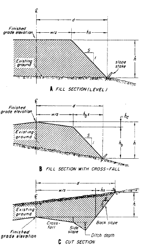
ft from the slope stakes. Refer back to figure 14-31 and take a close look at the position of the slope stakes. The horizontal distance of a slope stake from the center line varies, and to determine what it is, you must know three things.1. The width of the roadbed, including widths of shoulders and ditches, if any2. The side-slope ratio (expressed in units of horizontal run in feet per foot of vertical rise or fall)3. The difference in elevation between the grade for the road and the point on the natural ground line where the slope stake will be set In figure 14-37, view A, d is the horizontal distance from the center line to the slope stake, W/2 is the horizontal distance from the center line to the top of the slope, h is the difference in elevation between the finished grade and the ground at the slope stake, ands is the slope ratio.The product of h x s gives the run of the slope; that is, the horizontal distance the slope covers. The horizontal distance (d) of the slope stake from the center line, then, equals the sum of W/2 plus hs. For example, suppose that W/2 is 20 ft, h is 10 ft, and the bank is a 4:1 slope. Then
and
In practice, you may have to take other factors into account, such as transverse slope or the crossfall of the pavement (sometimes called the crown), ditches, and so on. In figure 14-37, view B, for example, there is a crossfall (h=) across W/2 so that the run (horizontal distance covered) of the bank (hbs) is the product of s x hb instead of hs, as in figure 14-31, view A. The crossfall is usually constant and may be obtained from the typical design sect ion shown on the plans. Figure 14-37, view C, shows a cut section in which W/2 varies with crossfall, side slope, ditch depth, and back slope. For example, assume that the distance from the center line to the beginning of the side slope is 20 ft, that the cross fall totals 1 ft, that ditch depth is 1.5 ft, and that both the side slope and back slope ratios are 2:1. The distance W/2, then, comprises horizontal segments as follows: 1. From the center line to the top of the slope which is 20 ft
Figure 14-37.-Determining slope stake location (distance from center line) for a proposed roadway.2. Then to the ditch flow line, which equals the product of slope ratio (2) times ditch depth (1.5), or 3 ft3. Then to the point on the back slope that is level with the finished center line, which equals slope ratio (2) times difference in elevation; that is, crossfall plus ditch depth,
The total distance, W/2, then, is the sum of
|
 |
|
|
||