|
SECTION LINES Sometimes the technical information conveyed by
a drawing can best be shown by a view that represents
the object as it would look if part of it
were cut away. A view of this kind is called a section.
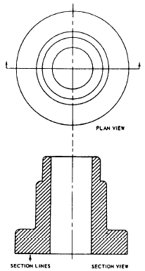
The upper view of figure 3-37 shows a plan view
of a pipe sleeve. The lower view is a section,

Figure 3-37.-Drawing of a plan view
and a full section.
showing the pipe sleeve as it would look, viewed from
one side, if it were cut exactly in half vertically.
The surface of the imaginary cut is crosshatched
with lines called section lines. According
to DoD-STD-100C, "section lining shall
be composed of uniformly spaced lines at an
angle of 45 degrees to the baseline of the section.
On adjacent parts, the lines shall be drawn in
opposite directions. On a third part, adjacent to
two other parts, the section lining shall be drawn
at an angle of 30 to 60 degrees." The
cross-hatching shown in figure 3-37 could be
used on any drawing of parts made of only one material
(like machine parts, for example, which are
generally made of metal). The cross-hatching is
the symbol for metals and may be used for a section
drawing of any type of material.
A section like the one shown in figure 3-37, which
goes all the way through and divides the object
into halves, is called a full section. If the section
showed the sleeve as it would look if cut vertically
into unequal parts, or cut only part way through,
it would be a partial section. If the cut followed
one vertical line part of the way down and
then was offset to a different line, it would be
an offset section.
|

|

