|
CIRCLES IN MULTI-VIEW ORTHO-GRAPHIC
PROJECTION.
A circle on a
surface
that is parallel to the plane of projection will
project as a circle. A circle on a surface that is
oblique to the plane of projection, however, will project
as an ellipse, as shown in figure 5-21. The upper
view in this figure is a top view of a wedge, the
wedge having a hole bored through it perpendicular
to the inclined face. The outline of this
hole on the front face of the wedge projects as
an ellipse in the front view. You get the minor axis
of the ellipse by projecting downward as shown.
The length of the major axis is equal to the
diameter of the hole. Another ellipse is shown in the front view. This
is the partly hidden and partly visible outline of
the hole as it emerges through the back of the wedge.
The back of the wedge is parallel to the front
view plane of projection; therefore, this ellipse
is the true outline of the hole on the back of
the wedge. The outline is elliptical because the hole,
though it is circular, is bored obliquely to the
back face of the wedge.
To draw these ellipses, you could use any of
the methods of drawing an accurate ellipse
explained
in the previous chapter on geometric construction,
or you could use an ellipse template.
AUXILIARY VIEWS. In
theory, there are only three
regular planes of projection: the
vertical, the horizonal, and the profile. Actually,
it is presumed that each of these is, as it
were, double; there is, for example, one vertical
plane for a front view and another for a
back view.
We assume, then, a total of six regular planes of
projection. A projection on any one of the six is
a regular view. A projection NOT on one of the
regular six is an AUXILIARY VIEW.
The basic rule of dimensioning requires that a
line be dimensioned only in the view in which its
true length is projected and that a plane with its
details be dimensioned only in the view in which
its true shape is represented. To satisfy this rule,
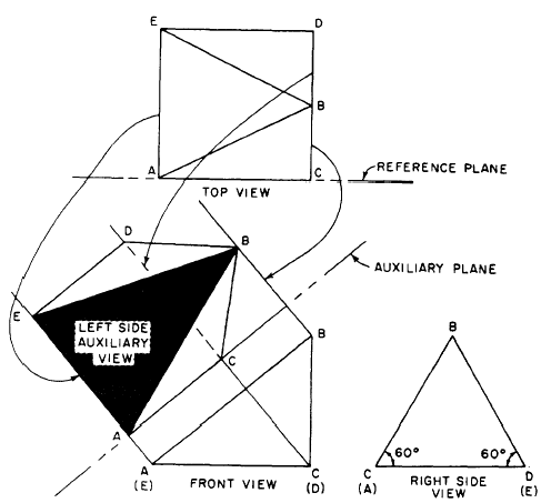
we have to create an imaginary plane that is
parallel with the line or surface we want to project
in its true shape. A plane of this kind that
is not one of the regular planes is called an AUXILIARY
PLANE.
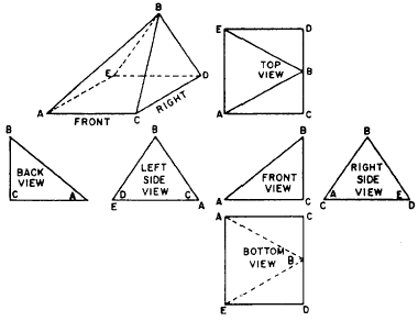
In the upper left of figure 5-22, there is a single-view
projection of a triangular block, the
base of which is a rectangle. This block is presumed
to be placed for multi-view projection

Figure 5-22.-A line oblique to all
planes of projection is foreshortened in all views.

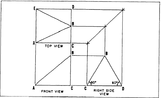
Figure 5-23.-Normal multi-view
projection.

Figure 5-24.-Projection of left side
auxiliary view.
with the right side parallel to the
profile plane. The block is then
drawn, using all six views of multi-view
projection.
By careful examination of figure 5-22, you will see
that the lines AB, AE, BD and BC and the surfaces
ABC, ABE, and BDE are oblique to three
regular planes of projection. The lines are foreshortened
and the surfaces are not shown in their
true shape in any of the six normal views.
The first step in the drawing of any auxiliary view
is to draw the object in normal multi-view projection,
as shown in figure 5-23. A minimum of
two orthographic views is necessary. The space between
these views is generally greater than normal.
The reason for this will become apparent. Notice
in figure 5-23, in the front view, that A is
the end point of line AE (top view) and C is the
end point of CD.
|
|

