Custom Search
|
|
 
|
||
|
REVOLVED SECTIONS. A
common use of the revolution is the
revolved section, shown in figure
5-29. At the top of this figure, there is a
single projection of a triangular block. You can show
all required information about this block in a
two-view projection by including a revolved section in
the front view as shown. You first assume that
the block is cut by a plane perpendicular to the
longitudinal axis. You then revolve the resulting
section 90 degrees on an axis perpendicular to
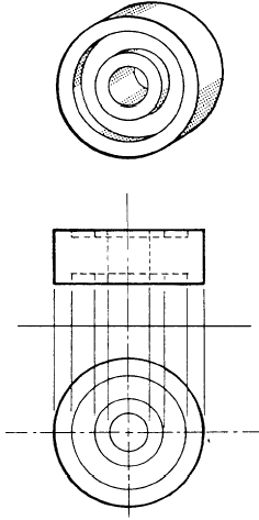
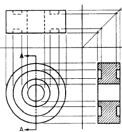
the horizontal plane of projection. SECTIONING TECHNIQUES. A sectional view is called for when the internal structure of an object can be better shown in such a view than it can by hidden lines. In the upperpart of figure 5-30, there is a single-view projection of a pulley. The same object is shown below in a two-view multi-view projection. The internal structure of the pulley is shown by the hidden lines in the top view. In figure 5-31, the internal structure of the pulley is much more clearly shown by a sectional view. Note that hidden lines behind the plane of projection of the section are omitted in the
Figure 5-30.-Internal structure of hidden lines. an object shown by
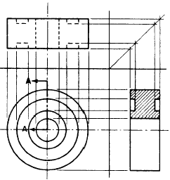
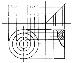
Figure 5-31.-Internal structure of an object more clearly shown by sectional view. sectional view. These lines are omitted by general custom, the custom being based on the fact that the elimination of hidden lines is the fundamental reason for making a sectional view. However, any lines that would be VISIBLE behind the sectional plane of projection must be included in the sectional view. The section shown in figure 5-31 is called a FULL SECTION because the cutting plane passes entirely through the object and divides it into two equal parts. Also, the object shown in figure 5-31 is a symmetrical objectmeaning, in general, that the shape of one half is identical to the shape of the other. This being the case, you could have used a HALF SECTION like the one shown in figure 5-32. This half section constitutes one half of the full section. Because the other half of the full section would be identical with the half shown, it need not be drawn. Note that a center line, rather than a visible line, is used to indicate the division between the sectioned and the unsectioned part of the sectional view. A visible line would imply a line that is actually nonexistent on the object. Another term used in place of center line is LINE OF SYMMETRY. A section consisting of less than half a section is called a PARTIAL SECTION. (See fig. 5-33.) Note that here you use a break line to indicate the division between the sectioned and unsectioned part. For this reason, a partial section is often called a BROKEN SECTION. The section lines drawn on a sectional surface always serve the basic purpose of indicating the limits of the sectional or cutaway surface. They may also indicate the type of material of which
Figure 5-32.-Use of half section.
Figure 5-33.-Use of partial or broken section. the sectioned surface consists. For example, in figure 5-34, view A shows section lining for an object made of cast iron. View B shows two matching parts made of steel, and view C shows three adjacent parts made of brass, bronze, or copper. For other symbolic section lining symbols, refer to ANSI Standard Y14.2. |
 
|
|
|
||
|
|
Integrated Publishing, Inc. - A (SDVOSB) Service Disabled Veteran Owned Small Business
|