|
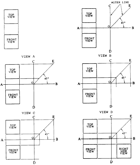
Figure 5-9 shows the basic principles of the
method by which you would actually make
the projection shown in figure 5-8. Draw
a horizontal line AB and a vertical line
CD, intersecting at O. AB represents the
joint between the horizontal and the vertical
plane; CD represents the joint between these
two and the profile plane. Any one of
the three views could be drawn first, and
the other two projected from it. Assume that
the front view is drawn first on the basis
of given dimensions of the front face. Draw
the front view, and project it upward with
vertical projection lines to draw the top
view. Project the top view to CD with horizontal
projection lines. With O as a center,
use a compass to extend these projection lines
to AB. Draw the right side view by
extending the projection lines from AB
vertically downward and by projecting the
right side of the front view horizontally to
the right. 
Figure 5-10.-Use of a miter line.
|


|

