|
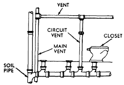
A CIRCUIT VENT serves a group of fixtures. As
shown in figure 8-21, a circuit vent extends from
the main vent to a position on the horizontal
branch between the last two fixture connections.
If more than eight fixtures are to be vented,
an additional circuit vent is to be installed. In
this type of vent, water and waste discharged 
Figure 8-21.-Use of a circuit vent.
by the last fixture tend to scour the vents of other fixtures
on the line.
When liquid wastes flow through a portion of a
vent pipe, the pipe is known as a WET VENT. A
LOOP VENT is the same, except that it connects
into the stack unit to form a loop. This type
may be used on a small group of bathroom fixtures,
such as a lavatory, water closet, and shower,
as shown in figure 8-22. The pipe for a wet
vent installation should be sized to take care of
the lavatory, water closet, and shower.
NOTE: The pipe for a wet vent installation should
never be under 2 in. in diameter when it will
be draining more than four fixture units. A water
closet should not drain into a wet vent. As
shown in figure 8-22, the lavatory should be
individually vented. This is necessary to prevent
loss of the trap seal through indirect siphonage.
Another point to note is that the relatively
clean water discharged from the lavatory will
tend to scour the wet vent, preventing an excessive
buildup of waste material in the vent. Materials
used in vent piping ordinarily include
galvanized pipe, cast-iron soil pipe, and, at
times, brass, copper, and plastic piping. In
all phases of the venting system, it is best to
use proper-sized piping. Remember that the diameter
of the vent stack or main vent must be no
less than 2 in. The actual diameter depends on
the developed length of the vent stack and on the
number of fixture units installed on the soil or
waste stack. The diameter of a vent stack should
be at least as large as that of the soil or waste
stack.

Figure 8-22.-Use of a wet vent.
|
|

