Custom Search
|
|
 
|
||
|
CHAIN
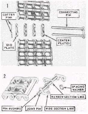
MECHANISMS In some engines, chains are not only used to drive camshafts and auxiliaries but also to drive such parts as rotating supercharger valves. Connecting links for two types of chains are shown in figure 3-27. Note that the connecting pins in one are secured by cotter pins, while the joint pins shown in the other are riveted. The principal causes of drive chain failure are improper chain tension, lack of lubrication, sheared cotter pins or improperly riveted joint pins, and misalignment of parts, especially idler gears. Chain drives should be checked for any symp-toms of such difficulties, in accordance with the instructions in the appropriate engine manual. The tension should be adjusted as required during
Figure 3-27.Accessory drive chain link assemblies. these inspections. An idler sprocket and chain tightener are used on most engines to adjust chain tension. During operation, chains increase slightly in length because of stretch and wear. Ad-justments should be made for these increases whenever necessary. When you are installing a new chain, peen the connecting link pins into place, but avoid excessive peening. After peening, make sure the links move freely without binding in position. Cotter pins must be secured or the joint pin ends riveted, whichever is applicable. Repair links should be carried at all times. Always check engine timing after installing a new timing and accessory drive mechanism. |
 
|
|
|
||