Custom Search
|
|
 
|
||
|
MAINTENANCE
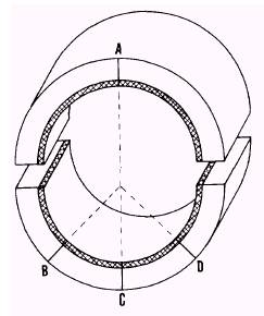
OF REDUCTION GEARS Under normal conditions, all repairs and major maintenance on main reduction gears should be accomplished by a naval shipyard. However, when the services of a shipyard are not available, emergency repairs should be accomplished (where possible) either by a repair ship or at an advanced base. Minor inspections, tests, and repairs should be accomplished by the ships force. It is of utmost importance that the ship retain a complete record of the reduction gears from the time of commissioning. Complete installation data, furnished by the contractor, should be entered in prescribed records by the ships engineering personnel when the ship is at the con-tractors yard. They should include the crown thickness readings and the clearances of the original bearings, the thrust settings and clearances, and the backlash and root clearances for gear and pinion teeth. It is essential to have this information available at the time when the alignment must be checked. All repairs, adjustments, readings, and casualties should be reported in accordance with 3-M system procedures. All original bearing data, as well as all additional bearing measurements, should be entered in appropriate records. The manufacturers technical manual, which gives detailed information regarding repairs to be made to reduction gears, is furnished to each ship. Special tools and equipment are normally pro-vided on board ship for (1) lifting some reduc-tion gear covers, (2) handling the gear elements when removing or replacing their bearings, (3) making the required measurements, and (4) rebab-bitting bearings. These special tools and equipment should be available aboard ship in case repairs have to be made by repair ships or at advanced bases. Bridge gages are no longer used to check bearing wear of the main reduction gears. When bearing wear must be checked, the crown thickness method is used. A bearing shell consists of a pressure-bearing half and a nonpressure-bearing half. The nonpressure-bearing half has a radial scribe line at one end of the geometric center. The pressure-bearing half of every main reduction gear shell has three radial scribe lines on each end of the bearing shell (figure 4-1). As you can see one of these scribe lines is located at the geometric center of the shell and the remaining lines intersect the center scribe line at a 45 angle. The crown thickness of each shell at these points should be measured with a micrometer at a prescribed distance from the end of the shell. These measurements should be recorded during the initial alignment and should be permanently marked adjacent to each scribe line. The amount of bearing clearance should not be allowed to become too great to cause incor-rect tooth contact. The designed clearances for
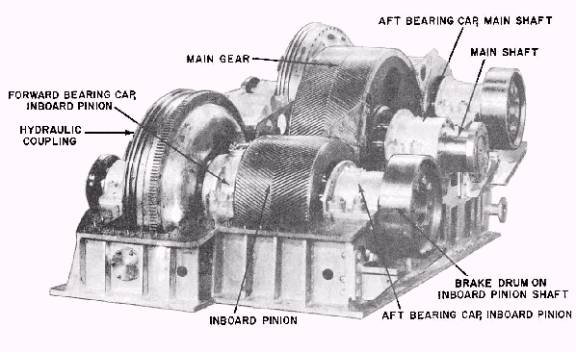
Figure 4-1.Scribe lines used in measuring the crown thickness of reduction gear bearings. bearings are given in the manufacturers technical manual. These clearances are also shown on the blueprints for the main reduction gears. On a multishaft ship, if a main reduction gear bearing is wiped, the preferred procedure (if prac-ticable) is to secure the shaft and the reduction gear until the units can be inspected and repaired by a repair activity. A glance at figure 4-2 will indicate why the replacement of a bearing in a main reduction gear would be a major undertaking for the ships force. However, emergency conditions may require action by the ships force. When such action is to be taken, a number of factors must be taken into consideration before repairs are attempted. The first factor to consider would be whether or not to attempt the repair work. The EN1 or the ENC must study the manufac-turers instructions and the blueprints for the reduction gear, so as to have a clear understanding of the constructions details and the repair pro-cedures and to be able to decide whether or not the work should be done by the ships force. Other factors which must be considered are the location
Figure 4-2.Starboard gear unit with cover removedview from aft and inboard. of the ship, the availability of Navy repair ac-tivities, and the operational schedule of the ship. CAUTION: No portion of the gear casing or its access openings, plugs, piping, or attached fix-tures shall be dismantled or removed without the specific authorization of the ships engineer officer. Refer to the gear shown in figure 4-2 during the following discussion. Assume that the after bearing for the inboard pinion has been wiped because of an obstructed oil passageway. When making repairs to this unit, ensure the propeller shaft is locked rigid and the lubricating oil is pumped from the sump BEFORE the bear-ing cap is disturbed. For the physical security of main reduction gears refer to Naval Ships Technical Manual chapter 9420 and current ships instructions. After removing the bearing cap, remove and inspect the upper half of the bearing. Then, with the aid of a special jack, roll out the lower half of the bearing. The function of the jack is to relieve the weight from the lower half of the bearing and to properly support the rotating elements when the journal bearings are removed. The journal surface of the shaft and all oil passages (nozzles) should be carefully inspected and cleaned. The new bearing to be used to replace the wiped one should also be cleaned and inspected. Its crown thickness, as measured at the factory, is stamped on the new bearing. The measurements of the new bearing should be com-pared with those of the original bearing and with the specifications in the manufacturers instructions. After ensuring that the new bearing is well oiled, the lower half of the bearing can be rolled into place and the jack removed. Then the upper half is placed in position. Be sure that the bear-ing and its dowel are in the required position, and in accordance with the manufacturers instructions. Afterwards, the bearing cap can be lowered into position and securely bolted down. It is possible that the forward bearing for the inboard pinion is also damaged as a result of excessive wear. When one pinion bearing fails, that end of the shaft will tend to move away from the bull gear; consequently, an abnormal load will be placed on the other pinion bearing. For this reason, the other pinion bearing should also be opened and inspected, and checked with a micrometer, using the crown thickness method. All readings should compare with the readings listed in the manufacturers instructions. If excessive wear is indicated, the bearing should be replaced with a new one. If no wear of the opposite pinion bearing is indicated, then the for-ward bearing can be reassembled. The condition of the bearings depends a great deal upon the type of casualty that has occurred. When the casualty is due to a loss of lubricating oil, the pinion bearings must be checked first. If these bearings are in good condition, it may be assumed that the bull gear shaft bearings are also in satisfactory condition. However, after a bear-ing casualty has been corrected, a close watch should be maintained on all bearings. Remember that when the reduction gear is opened, every precaution should be taken to keep out dirt and foreign matter and that the repair personnel should remove all loose articles from their clothing. Again, before closing the reduction gear, a careful inspection should be made to see that the inside of the gear is free of all dirt, foreign matter, and misplaced tools. |
 
|
|
|
||
|
|
Integrated Publishing, Inc. - A (SDVOSB) Service Disabled Veteran Owned Small Business
|